-
高氮钢是工程材料中的一个重要分支,氮在高氮钢中的作用是部分甚至全部替代合金元素镍来获得单相奥氏体组织[1-2]。高氮钢主要应用于工程结构材料,它的应用范围很大程度上取决于其焊接性好坏[3-5]。焊接工艺和焊接材料的合理选择是解决焊接问题的关键[6],直接影响高氮钢的应用前景。近年来,国内外的焊接学者深入研究了高氮钢焊接技术并取得了阶段性成果。
激光焊接是一种先进的焊接技术,其加热和冷却速度快、热影响区较窄,是钢铁材料焊接的最有效方法之一[7-9]。DU等人[10-11]的研究表明,高氮钢焊缝与热影响区组织为奥氏体和δ铁素体,并且冷却速度越快,高温停留的时间越长,δ铁素的体总量就越多。ZHAO等人[12-13]对高氮钢激光焊接的组织和性能进行了研究,结果表明,焊缝和热影响区组织为奥氏体和δ铁素体,均没有出现软化区。LAMBOLIEV等人[14]利用CO2激光焊接了质量分数分别为0.18,0.006,0.12的Cr,N和Mn的高氮钢,发现采用N2作为保护气体时焊缝中的氮含量比Ar保护时高,并且接头中氮含量越高,拉伸性能越好。LI等人[15]对高氮钢焊缝冲击断口的分析表明,断口均在富含δ铁素体的位置开裂,撕裂界面呈“骨架状”,裂缝短且较深。
目前,高氮钢的焊接仍然以传统的熔化焊为主,激光及其复合焊接、搅拌摩擦焊接等先进的焊接技术也已在高氮钢的焊接中开始应用[16-17]。本文中采用激光-电弧复合焊接技术对高氮钢板进行了焊接,研究了焊接接头的微观组织及力学性能,并分析了其断裂机理,揭示了焊接条件对焊接接头组织和力学性能的影响规律,旨在为激光-电弧复合焊接在高氮钢焊接领域的应用奠定基础。
-
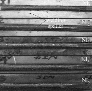
试验过程中以高氮奥氏体不锈钢为焊接试验钢板,焊接效果如图 1所示。本文中选用的是焊接工艺参量相对最佳的NI3(作者编号)作为研究对象。焊接方式采用平板对接,对接焊试板尺寸为400mm×100mm×8mm,板面开坡口角,Y型坡口,取单边坡口角为15°, 钢板对接间隙为0.6mm,钝边高度为5mm。焊丝采用的是直径为1.2mm的不锈钢焊丝,高氮钢和焊丝的主要化学成分见表 1。
Table 1. The main chemical compositions of high nitrogen steel and wire(mass fraction)
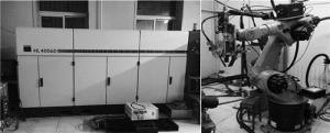
C Cr Ni Mn N Si high nitrogen steel 0.0015 0.2200 0.0047 0.1600 0.0075 0.0049 wire 0.01 0.20 0.10 0.07 0 — 采用额定功率为4kW的Nd: YAG固体激光器(如图 2所示),激光垂直于工件表面,焦距为235mm,采取负离焦的工作形式,离焦量为-2mm;采用日本松下公司的YD-350AG2HGE型MIG/MAG焊机,发散角为2mrad,保护气体用体积分数分别为0.90,0.10的Ar和CO2,流量为18L/min,采用的主要工艺参量见表 2。
Table 2. Process parameters of composite welding
laser power welding speed arc voltage welding current wire spacing defocused 2.6kW 0.8m/min 26.0V 220A 3mm -2mm 焊后用LeicaDM2700M型金相显微镜及扫描电子显微镜(scanning electron microscope, SEM)等对焊接接头组织进行观察,并利用LED-2300型电子能谱仪对焊缝内的条状物和基体及第二相进行能谱分析仪(energy dispersive spectroneter, EDS)的能谱分析,并进一步利用Empyrean型X射线衍射系统进行物相分析,在8850型试验机上进行焊接接头拉伸性能测试,并对断口进行SEM分析。拉伸试件尺寸如图 3所示。
-
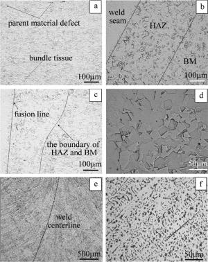
图 4a为高氮钢母材(base metal, BM)的微观组织,可以清晰地看到母材的组织为纯奥氏体,并且为颗粒相对细小均匀的等轴奥氏体,其中有部分孪晶分布,同时观察到有部分黑色小斑点,为轧制时产生的缺陷。仔细观察还可发现,奥氏体晶粒出现束状组织,且不同束状组织各具方向性。
图 4b为焊接接头的全貌,右侧为母材,靠近中间位置偏左的区域为热影响区(heat affected area, HAZ),此区域是母材和焊缝的过渡区域。从图 4c中可以看出, 母材和热影响区的分界线并不明显,并且热影响区的范围呈现上宽下窄的特点。由于焊接过程中受热源的影响而变化,可以清晰地看出与右侧母材的区域相比热影响区晶粒略显粗大,并且颗粒大小分布不均匀,呈现为较大颗粒的奥氏体组织。图 4d中为热影响区粗大的奥氏体晶粒,这是由于激光-电弧复合焊接条件下,热影响区受到强烈的过热影响而促使晶粒发生严重的长大,晶粒粗化不但影响接头的性能,同时有产生裂纹的风险。晶粒粗化对奥氏体的分解以及转变产物等都有很大影响,晶粒越粗大,奥氏体之间的晶界面积就越小,从而使形核的机会减少,不利于奥氏体的进一步转变。
图 4e为低倍镜下焊缝中心的组织形貌,可以看到晶粒以弯曲的形状向焊缝中心生长。图 4f为高倍镜下焊缝中心的组织形貌。由于焊接的特点,使焊缝区域温度梯度较大,过冷速度较快,当晶粒生长方向与熔池散热方向相反时,将会阻碍奥氏体晶粒的正常生长,使熔池稳定后的焊缝金属为树枝晶和尺寸不一的多边形奥氏体晶粒同时存在。并且由于焊缝区的下部主要是激光匙孔作用产生的,此部位激光作用较大,熔池较小,并且由于激光具有细化晶粒的作用,使此部分晶粒向激光作用方向均匀生长。但温度梯度的影响不利于等轴晶的生长,所以焊缝中心的等轴晶组织形貌并不十分明显。通过对焊缝中心形貌的进一步观察,可以发现焊缝区主要是树枝晶和少量的等轴晶。
根据金属凝固学理论[18],晶体形态主要取决于以下3点:液态金属中的溶质浓度C、结晶速率R和液态中的温度梯度G。随着熔池凝固(结晶)的进行,固液界面从焊缝边缘不断向焊缝中心发展,液态中的G不断变小,R逐渐增大,杂质和合金元素在焊缝中心出现偏析,使C变大。由于激光-电弧复合焊接热源大,能量密度较高,焊缝中心处的峰值温度高,与焊缝边缘的温度梯度大,冷却速度快,使成分过冷变大,所以随着熔池结晶过程的进行,焊缝边缘到焊缝中心的结晶状态从柱状晶向树枝晶转变。
-
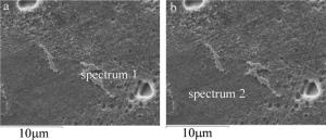
为了更清楚地了解焊缝内的组织形貌,分别对焊缝内的条状物和基体做了EDS能谱分析,条状物和基体分别取为谱图 1和谱图 2,如图 5a、图 5b所示。EDS能谱分析的结果如表 3所示。
Table 3. The results of energy spectrum analysis in different areas in weld seam(mass fraction)
area Cr Mn Fe Ni spectrum 1 0.2544 0.1062 0.6093 0.0301 spectrum 2 0.2048 0.1533 0.5958 0.0461 从表 3中两区域的能谱分析结果可以看出,相对于谱图 2,谱图 1的Cr质量分数所降低,而Mn的质量分数有所升高。众所周知,合金元素可以提高钢的综合性能,并且合金元素的加入对铁碳合金相图、相变温度、共析成分等都有一定的影响。奥氏体的单相区会随着合金成分质量分数的多少而扩大或缩小。Mn为奥氏体形成元素,可使奥氏体相区扩大,而Cr为铁素体形成元素,可使奥氏体相区缩小。由谱图的合金质量分数分析可知,在同一焊缝区域,条状物谱图 1的Cr质量分数高于基体谱图 2的Cr质量分数,而条状物谱图 1的Mn质量分数低于基体谱图 2的Mn质量分数,说明了条状物中铁素体相较强,而基体中奥氏体相较强。所以由合金质量分数可以判定焊缝内的条状物组织可能为铁素体,而条状物呈现在焊缝中的形貌较少,说明焊缝中含有铁素体但质量分数较少。通过对焊缝的EDS能谱分析,说明合金元素的质量分数对焊缝形貌有一定的影响。
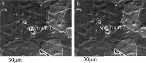
通过扫描电子显微镜观察焊缝区域组织,进一步观察可以看到,焊缝区域有微小坑状形貌,并且周围有细小颗粒的第二相粒子出现。为了更深入研究焊缝的组织形貌特点,对这两个质点进行EDS能谱分析,谱图 1为近似方形的质点,谱图 2为近似球形的质点,如图 6所示,成分分析如表 4所示。
Table 4. Energy spectrum analysis of the second phase particle with different particles in weld seam(mass fraction)
area Cr Mn Fe Ti Al Mg Si O spectrum 1 0.1223 0.3179 0.1398 0.1424 0.0220 0.000 0.000 0.2556 spectrum 2 0.1793 0.2300 0.3768 0.0142 0.1670 0.0207 0.0120 0.000 由EDS图表分析可知,第二相粒子中的Mn元素质量分数相比于焊缝内条状物和基体的质量分数明显高一些,而Cr的质量分数略低于焊缝基体,并且Fe元素的质量分数明显低于焊缝基体。由于Mn的强化作用强烈,会使奥氏体区扩大,细化奥氏体晶粒,从而可以确定焊缝中的第二相粒子有细化晶粒的作用,可提高焊缝强度。由第二相粒子谱图 1和谱图 2的元素质量分数比较分析可得:谱图 1中含O元素而谱图 2中无O元素;谱图 1中的Ti元素、Mn元素质量分数高于谱图 2;但是谱图 1中的Fe元素明显低于谱图 2。从谱图 1和2的元素质量分数对比可以看出:谱图 1由于氧元素的存在很有可能存在氧化物;而Ti的质量分数高于谱图 2说明抑制奥氏体晶粒长大更明显一些。在一般情况下,夹杂物中的Al, Mn, Si以氧化物、硅酸盐、尖晶石(MnAl2O4)等形式存在,而质点1的方形粒子,根据Ti元素和O元素的质量分数比较,很可能是以Ti的氧化物TiO2存在,并且还可能含有尖晶石(MnAl2O4)等成分。而谱图 2的球形颗粒含有Al, Mg, Ti, Si等多种合金元素,这类颗粒可能为硅酸盐或者是氧化物的夹杂物,而球形第二相谱图 2无O元素,所以很可能为硅酸盐。一般情况下焊缝中的夹杂物主要由外界的焊丝、焊剂或者通过冶金反应产生,但是据EDS能谱分析,夹杂物中含Mg, Al, Si, Ti等合金元素,而所用焊丝中无此元素,所以断定夹杂物主要是通过冶金反应产生。进一步对谱图 1中的夹杂物成分进行分析,由于Al是很强的脱氧剂,它先与O反应生成Al2O3,Mn的脱氧能力较低,于是Al2O3和MnO结合形成更稳定的MnAl2O4化合物。
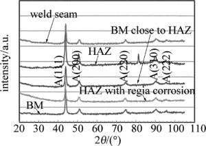
为了更清楚地分析焊接接头的组织,更好地了解其力学性能等因素,对焊缝接头的多个部分做了XRD衍射分析。对试样衍射完成后,利用数据软件解析出焊接接头各区域的谱线图,从而进行物相峰位角度、相对强度等的定性分析。试验结果如图 7所示,图中A代表奥氏体,括号内数值表示晶面指数(无单位)。
利用物相分析软件Jade与标准的奥氏体组织的衍射特征值比较,衍射角匹配。由图 7中可以看出, 无论是母材、热影响区还是焊缝,全部是奥氏体组织(实际的SEM组织观察表明,无论是母材还是焊缝,或者有少量的铁素体组织(质量分数小于0.05)和少量析出的珠光体似的Cr2N析出物,因量太少,未能出现在X射线的衍射峰值上)。结合焊缝区域的微观图,可知焊缝区为细小的树枝状晶粒,并伴有少量铁素体的形成。
-
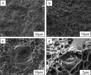
通过拉伸试验可以发现,拉伸断裂的位置均出现在焊缝区,这是由于在一般熔焊中,焊缝中氮的损失较大以及焊缝中气孔裂纹等缺陷的出现,导致焊缝区的平均强度降低。试验中测得拉伸断裂的强度达到952.36MPa,拉伸断口的微观形貌如图 8所示。
由图 8可以看出,拉伸断裂的断口在扫描电子显微镜下的微观组织形貌类似于蜂窝状。以韧窝为断口形貌是金属塑性断裂的重要微观特征,它是通过金属材料在微小区域内的塑性变形而产生空洞的洞核,彼此之间通过长大聚集连接后宏观体现为断裂面的一种韧性断裂机制,宏观体现为纤维状,微观呈现为蜂窝状。可以通过深度和平均直径来确定韧窝的大小,韧窝的深浅和大小主要是由第二相粒子的大小和密度分布以及塑性变形能力来决定,从外界来看则主要是由拉伸力的加载速度和应力大小来决定。一般情况下,在断裂条件相同时,韧窝越大说明金属的塑性越好。从图 8b中可以看到有明显的韧窝,是典型的韧性断裂,大多数韧窝深度稍浅,有明显的方向性;韧窝花样中的白色线条为撕裂棱形貌,可以看出撕裂棱较低。从图 8a的断口中有一定量的微小孔存在,并且出现了一些空洞的现象。从图 8c、图 8d中可以看出较深的空洞形貌,这是由焊缝的气孔或裂纹源经受力拉伸形成的,空洞形貌类似于蛇形,并且空洞底部存在有第二相粒子或夹杂物。由于焊缝的氮含量相对较低,并且由于焊缝缺陷(如气孔或裂纹)致使焊缝区的强度低于其他区域,导致在外力拉伸时,裂纹先于焊缝处产生再向四处扩展,随着载荷的增加,缺陷处先断裂,造成无缺陷处受力不均匀,使得无缺陷处金属内部形成的大量显微空洞还来不及长大就已经被撕裂开,从而无缺陷处发生的塑性变形较小,形成的韧窝较浅且具有明显的方向性。
-
(1) 焊缝区的组织为典型的树枝晶和少量的等轴晶形貌,无论是母材、热影响区都是奥氏体组织,焊缝区除了奥氏体外还伴有少量的δ铁素体。
(2) 焊缝中的第二相粒子主要是通过冶金反应产生,以TiO2、尖晶石(MnAl2O4)以及硅酸盐等形式存在,对晶粒有明显的细化作用,可增加焊缝强度。
(3) 拉伸断裂出现在焊缝区,断口组织形貌为典型的韧窝断裂,并在断裂处可发现有空洞和第二相粒子的形貌特征,说明焊缝缺陷可能导致力学性能薄弱。
高氮钢复合焊接接头微观组织及力学性能
Microstructure and mechanical properties of composite welded joints of high nitrogen steel
-
摘要: 为了研究和掌握高氮钢复合焊接接头的微观组织和力学性能,以8mm厚的高氮钢板为试验材料,采用额定功率为4kW的Nd:YAG固体激光器对其进行了激光-电弧复合焊接,利用金相显微镜和扫描电子显微镜对焊接接头的微观组织和断口形貌进行拍照和分析,并利用能谱分析仪和X射线衍射仪,从微区成分元素的种类、含量及物相组成方面进一步分析母材、热影响区、焊缝区的微观组织。结果表明,焊缝区的组织为典型的树枝晶和少量的等轴晶形貌,母材、热影响区都是奥氏体组织,焊缝区除了奥氏体组织外还伴有少量的δ铁素体组织;焊缝中的第二相粒子主要是通过冶金反应产生,以TiO2、尖晶石(MnAl2O4)以及硅酸盐等形式存在,对晶粒有明显的细化作用,可增加焊缝强度;拉伸断裂出现在焊缝区,断口组织形貌为典型的韧窝断裂,并在断裂处可发现有空洞和第二相粒子的形貌特征,说明焊缝缺陷可能导致力学性能薄弱。此研究为激光-电弧复合焊接在高氮钢焊接领域的应用奠定了一定基础。
-
关键词:
- 激光技术 /
- 高氮钢激光-电弧复合焊接 /
- 微观组织 /
- 力学性能
Abstract: In order to study the microstructure and mechanical properties of welded joints of high nitrogen steel, high nitrogen steel plate with 8mm thickness was used as test material and Nd:YAG solid state laser with the rated power of 4kW was used to do laser-arc composite welding. The microstructure and fracture morphology of the welded joint were photographed and analyzed by a metallographic microscope and a scanning electron microscope. The microstructures of the base material, the heat affected zone and the welded zone were further analyzed in terms of element composition, content and phase composition by energy a spectrum analyzer and a X-ray diffractometer. The results show that the microstructure of the welded zone is typical dendrite and a small amount of equiaxial morphology. Both the base material and the heat affected zone are austenitic tissues.The welded zone is accompanied by a small amount of delta ferrite in addition to austenite tissues. The second phase particles in weld seam are mainly produced by metallurgical reaction in the form of TiO2, spinel (MnAl2O4) and silicate. It has obvious refinement to the grain and can increase the strength of weld seam. Tensile fracture occurs in the welded zone.Fracture morphology is typical of dimple fracture. The morphology of the cavity and the second phase particles can be found at the fracture. It is indicated that weld defects may lead to weak mechanical properties. The study lays a foundation for the application of laser-arc composite welding in the field of high nitrogen steel welding. -
Figure 4. Microstructure of welded joints
a—microstructure of high nitrogen steel matrix b—overall microstructure of welded joints c—peripheral microstructure of welded joint d—coarse austenite grains of heat affected zone e—microstructure of weld seam with low magnification f—microstructure of weld center with high magnification
Table 1. The main chemical compositions of high nitrogen steel and wire(mass fraction)
C Cr Ni Mn N Si high nitrogen steel 0.0015 0.2200 0.0047 0.1600 0.0075 0.0049 wire 0.01 0.20 0.10 0.07 0 — Table 2. Process parameters of composite welding
laser power welding speed arc voltage welding current wire spacing defocused 2.6kW 0.8m/min 26.0V 220A 3mm -2mm Table 3. The results of energy spectrum analysis in different areas in weld seam(mass fraction)
area Cr Mn Fe Ni spectrum 1 0.2544 0.1062 0.6093 0.0301 spectrum 2 0.2048 0.1533 0.5958 0.0461 Table 4. Energy spectrum analysis of the second phase particle with different particles in weld seam(mass fraction)
area Cr Mn Fe Ti Al Mg Si O spectrum 1 0.1223 0.3179 0.1398 0.1424 0.0220 0.000 0.000 0.2556 spectrum 2 0.1793 0.2300 0.3768 0.0142 0.1670 0.0207 0.0120 0.000 -
[1] BEMS H. Manufacture and application of high nitrogen steels[J]. ISIJ International, 1996, 36(7):909-914. doi: 10.2355/isijinternational.36.909 [2] LI Zh R, ZHANG J H, FENG J C, et al. Study on diffusion connection process of tin bronze-nickel-steel[J]. Welding Technology, 1999, 6(2):6-7(in Chinese). [3] HARZENMOSER M. Welding of high nitrogen steels[J]. Materials and Manufacturing Process, 2004, 19(1):77-86. [4] WOO I, KIKUCHI Y. Weldability of high nitrogen stainless steel[J]. ISIJ International, 2002, 42(12):1334-1343. doi: 10.2355/isijinternational.42.1334 [5] SONG X H, JIN X Zh, CHEN Sh Q, et al. Laser-arc hybrid welding and its application in body manufacturing[J]. Laser Technology, 2015, 39(2):259-265(in Chinese). [6] GAO M, ZENG X Y, YAN J, et al. Laser-arc hybrid welding heat source interaction[J]. Laser Technology, 2007, 31(5):465-468(in Chinese). [7] PENG Y, WANG Ch, CHEN W Zh, et al. Laser welding of two kinds of ultra-fine grain steel[J]. Transactions of the China Welding Institution, 2001, 22(1):31-35(in Chinese). [8] HANG X D, CHEN W Zh, WANG Ch, et al. Microstructures and toughness of weld metal of ultra-fine grained ferritic steel by laser welding[J]. Journal of Materials Science & Technology, 2004, 20(6):755-759. [9] ZHAO L, CHEN W Zh, ZHANG X D, et al. Microstructure and properties of heat affected zone of new generation ultra-low carbon bainitic steel[J]. Chinese Journal of Lasers, 2006, 33(3):408-412(in Chinese). [10] DU W Sh, PENG Y, ZHAO L, et al. Microstructure and mechanical properties of MIG-welded joint of high nitrogen austenite stainless steel[J]. Welding & Joining, 2008, 2(10):25-29(in Chinese). [11] DU W Sh, ZHAO L, TIAN Zh L, et al. Microstructure of heat affected zone of 1Cr22Mn15N with high nitrogen austenitic stainless steel[J]. Transactions of the China Welding Institution, 2007, 28(7):1-4(in Chinese). [12] ZHAO L, TIAN Zh L, PENG Y, et al. Laser welding of high nitrogen steel 1Cr22Mn16N Ⅲ. Microstructure and mechanical properties of welding heat affected zone[J]. Transactions of the China Welding Institution, 2007, 28(12):26-30(in Chinese). [13] ZHAO L, TIAN Zh L, PENG Y, et al. Laser welding of high nitrogen steel 1Cr22Mn16N Ⅱ. Microstructure and mechanical properties of weld metal[J]. Transactions of the China Welding Institution, 2007, 28(9):80-82(in Chinese). [14] LAMBOLIEV T, ZUMBILEV A, CHRISTOV S, et al. Laser beam welding of high-nitrogen-containing austenitic stainless[J]. Welding Journal, 1999, 78(7):245-252. [15] LI D J, LU Sh P, LI D Zh, et al. Investigation of the microstructure and impact properties of the high nitrogen stainless steel weld[J]. Acta Metallurgica Sinica, 2013, 49(2):129-136(in Chinese). doi: 10.3724/SP.J.1037.2012.00514 [16] SUN Sh, LIU Sh Y, JIA D Sh, et al. Multiple nonlinear regression model of weld bead shape for high nitrogen steel by laser-arc hybrid welding[J]. Journal of Mechanical Engineering, 2015, 51(8):67-75(in Chinese). doi: 10.3901/JME.2015.08.067 [17] LI H B, JIANG Z H, FENG H, et al. Microstructure mechanical and corrosion properties of friction stir welded high nitrogen nickel-free austenitic stainless steel[J]. Materials & Design, 2015, 84(5):291-299. [18] ZHANG W Y. Welding metallurgy[M]. Beijing:Machinery Industry Press, 1996:123-127(in Chinese). -


 网站地图
网站地图

 下载:
下载:
