Advanced Search

ISSN1001-3806 CN51-1125/TN Map

Volume 44 Issue 3
Jul.  2020
Article Contents
Turn off MathJax

Citation:

Research on the on-line measurement of a birefringence fiber loop mirror strain sensor

  • Received Date: 2019-06-20
    Accepted Date: 2019-08-13
  • In order to realize the on-line measurement of a birefringence fiber (BF) loop mirror (Bi-FLM) strain sensor, the theoretical wavelength-demodulation on-line measurements expression of a Bi-FLM strain sensor was deduced. Two different groups of four-adjacent-wave-valley wavelengths near 1550nm and 1310nm were chosen and substituted into the theoretical expression. Both the calculated strains were basically consistent with the given strains. The result shows that the absolute BF length can be calculated by the random four-adjacent-wave-valley wavelengths, the initial BF length, the initial BF birefringence, and the initial strain dependent birefringence coefficient. Then the strain can be calculated according to the absolute BF length after axial strain and the initial BF length. According to the relative positions of any four-adjacent-wave-valley wavelengths which contained strain information, the noises or external sensing can be distinguished when the interference spectrum changes. By this way, the noises can be eliminated, and the measurement accuracy can be improved. These results can provide guidance for realizing the on-line measurement and improving measurement accuracy of the strain, vibration and other sensors of Bi-FLM.
  • 加载中
  • [1]

    JI Zh J, WU X N, YIN Y, et al. Tunable optical filters based on high birefringence fiber loop mirrors[J]. Laser Technology, 2014, 38(1):54-57(in Chinese).
    [2]

    JIANG Y, LIANG D K, ZENG J, et al. Influence of monitoring point wavelength on axial strain sensitivity of high-birefringence fiber loop mirror[J]. Acta Physica Sinica, 2013, 62(6):064216(in Chin-ese).
    [3]

    SUN G Y, TANG H J, HU Y H, et al. Strain and temperature discrimination using high birefringence fiber Sagnac interferometer with enhanced sensitivities[J]. IEEE Photonics Technology Letters, 2012, 24(7):587-589. doi: 10.1109/LPT.2012.2184087
    [4]

    JIANG Y, LIANG D K, LU J Y. Voltage demodulation and vibration monitoring based on a polarization maintaining fiber loop mirror[J]. Journal of Intelligent Material Systems and Structures, 2017, 28(13):1832-1838. doi: 10.1177/1045389X16679283
    [5]

    LEANDRO D, LOPEZ-AMO M. All-PM fiber loop mirror interfero-meter analysis and simultaneous measurement of temperature and mechanical vibration[J]. Journal of Lightwave Technology, 2018, 36(4):1105-1111. doi: 10.1109/JLT.2017.2761121
    [6]

    JIANG Y, ZENG J, LIANG D K, et al. The influences of polarization-maintaining fiber length and sensing length on axial strain sensitivity of polarization-maintaining fiber loop mirror[J]. Journal of Intelligent Material Systems and Structures, 2014, 25(15):1959-6194. doi: 10.1177/1045389X13512905
    [7]

    ZU P, CHAN C C, JIN Y X, et al. A Temperature-insensitive twist sensor by using low-birefringence photonic-crystal-fiber-based Sagnac interferometer[J]. IEEE Photonics Technology Letters, 2011, 23(13): 920-922. doi: 10.1109/LPT.2011.2143400
    [8]

    SILVA R M, FERREIRA M S, FRAZ${\rm{\tilde A}}$O O. Temperature independent torsion sensor using a high-birefringent Sagnac loop interferometer[J]. Optics Communications, 2012, 285(6): 1167-1170. doi: 10.1016/j.optcom.2011.11.119
    [9]

    THAKUR H V, NALAWADE S M, SAXENA Y, et al. All-fiber embedded PM-PCF vibration sensor for structural health monitoring of composite[J]. Sensors and Actuators: Physical, 2011, A167(2): 204-2012.
    [10]

    QIAN W W, ZHAO C L, DONG X Y. Intensity measurement based temperature-independent strain sensor using a highly birefringent photonic crystal fiber loop mirror[J].Optics Communications, 2010, 283(24): 5250-52544. doi: 10.1016/j.optcom.2010.07.062
    [11]

    JIANG Y, YU M J. Influence of birefringence fibre length on demodulation sensitivity based on a fibre loop mirror sensor[J]. IET Optoelectronics, 2018, 12(5): 254-257. doi: 10.1049/iet-opt.2018.5016
    [12]

    NOH T K, RYU U C, LEE Y W. Compact and wide range polarimetric strain sensor based on polarization-maintaining photonic crystal fiber[J]. Sensors and Actuators: Physical, 2014, A213(7): 89-93.
    [13]

    WU C, TSE M L V, LIU Z, et al. In-line microfluidic refractometer based on C-shaped fiber assisted photonic crystal fiber Sagnac interferometer[J]. Optics Letters, 2013, 38(17): 3283-3286. doi: 10.1364/OL.38.003283
    [14]

    GONG H P, SONG H F, ZHANG S L. Curvature sensor based on hollow-core photonic crystal fiber Sagnac interferometer[J]. IEEE Sensors Journal, 2014, 14(3): 777-779. doi: 10.1109/JSEN.2013.2283580
    [15]

    JIANG Y, ZHANG Ch Zh, LIANG D K, et al. Optimal research on the strain sensitivity of polarization maintaining fiber loop mirror[J]. Spectroscopy and Spectral Analysis, 2017, 37(5): 1576-1580(in Chinese).
    [16]

    ZHANG Y N, PENG H, ZHOU T, et al. Hydrogen sensor based on high-birefringence fiber loop mirror with sol-gel Pd/WO3 coating[J]. Sensors and Actuators: Chemical, 2017, B248:71-76.
    [17]

    WANG J, LIANG H, DONG X, et al. A temperature-insensitive relative humidity sensor by using polarization maintaining fiber-based Sagnac interferometer[J]. Microwave & Optical Technology Letters, 2013, 55(10):2305-2307.
    [18]

    ZHAO Ch L, WANG Zh, ZHANG Sh, et al. Phenomenon in an alcohol not full-filled temperature sensor based on an optical fiber Sagnac interferometer[J]. Optics Letters, 2012, 37(22):4789-4791. doi: 10.1364/OL.37.004789
    [19]

    ZHANG J, QIAO X, GUO T, et al. Highly-sensitive temperature sensor using a Hi-Bi fiber tip probe[J]. IEEE Sensors Journal, 2012, 12(6):2077-2080. doi: 10.1109/JSEN.2012.2183866
    [20]

    JIANG Y, LIANG D K, ZENG J, et al. Research on axial strain sensitivity of high-birefringence fiber loop mirrorr[J]. Spectroscopy and Spectral Analysis, 2012, 32(12): 3367-3371(in Chinese).
  • 加载中
通讯作者: 陈斌, bchen63@163.com
  • 1. 

    沈阳化工大学材料科学与工程学院 沈阳 110142

  1. 本站搜索
  2. 百度学术搜索
  3. 万方数据库搜索
  4. CNKI搜索

Figures(5) / Tables(2)

Article views(6110) PDF downloads(18) Cited by()

Proportional views

Research on the on-line measurement of a birefringence fiber loop mirror strain sensor

  • 1. College of Mechanical and Electronic Engineering, Nanjing Forestry University, Nanjing 210037, China
  • 2. College of Physics and Electronic Engineering, Xinyang Normal University, Xinyang 464000, China
  • 3. College of Intelligent Science and Control Engineering, Jinling Institute of Technology, Nanjing 211169, China

Abstract: In order to realize the on-line measurement of a birefringence fiber (BF) loop mirror (Bi-FLM) strain sensor, the theoretical wavelength-demodulation on-line measurements expression of a Bi-FLM strain sensor was deduced. Two different groups of four-adjacent-wave-valley wavelengths near 1550nm and 1310nm were chosen and substituted into the theoretical expression. Both the calculated strains were basically consistent with the given strains. The result shows that the absolute BF length can be calculated by the random four-adjacent-wave-valley wavelengths, the initial BF length, the initial BF birefringence, and the initial strain dependent birefringence coefficient. Then the strain can be calculated according to the absolute BF length after axial strain and the initial BF length. According to the relative positions of any four-adjacent-wave-valley wavelengths which contained strain information, the noises or external sensing can be distinguished when the interference spectrum changes. By this way, the noises can be eliminated, and the measurement accuracy can be improved. These results can provide guidance for realizing the on-line measurement and improving measurement accuracy of the strain, vibration and other sensors of Bi-FLM.

0.   引言
  • 双折射光纤环镜(birefringence fiber loop mirror,Bi-FLM)除了可以作为可调谐光滤波器之外[1],其在光纤传感领域的应用也引起了学者的广泛关注[2-3],已成功应用于振动[4-5]、应变[6]、扭矩[7-8]等测量。Bi-FLM传感器的测量原理是:外界条件变化使双折射光纤长度和双折射率发生变化,导致相角改变,从而使干涉光谱随之变化,以实现对外界条件变化的传感。目前,Bi-FLM传感器在线测量的方法主要是基于强度解调原理[9-11],即将Bi-FLM传感器的光信号强度通过光电转换器转换为电信号,通过监测电信号的变化反推光信号的变化,从而反推外界传感量的变化。由于强度解调受光源稳定性影响较大,因此该方法精度较低。Bi-FLM传感器离线测量绝大部分采用波长解调,即根据波长的相对变化量来推算传感量的大小[12-19]。基于波长解调的方法,克服了光源稳定性的影响,但在测量过程中,由于干涉光谱是周期性信号,需要人为判断:外界传感量的变化是导致干涉光谱左移还是右移,是传感量导致的较小相角变化产生的干涉光谱,还是传感量导致的更大的周期相角变化产生的周而复始的干涉光谱, 且在测试过程中, 外界干扰容易改变干涉光谱的初始相角,导致干涉光谱平移。基于波长解调的方法无法区分是:干扰还是外界传感量的变化导致的干涉光谱变化,致使测量精度下降。因此,基于波长解调的方法无法自动确定传感量唯一大小,无法实现在线测量,无法区分是干扰还是外界传感量的变化导致的干涉光谱变化, 且基于波长解调的方法需要选定监测点,通过监测点波长的变化反推应变的大小,监测点不同,同一Bi-FLM传感器灵敏度也各不相同[1, 12-13, 15], 不利于传感器的校准。

    本文中理论推导得出基于波长解调的表达式,可通过干涉光谱任意连续4个相邻的波谷波长及其双折射光纤初始信息计算双折射光纤所受轴向应变。该方法只需找到光谱中的任意连续4个最小值对应的波长,即可求解出应变,无需人为判断和校准,根据干涉光谱任意4个相邻波谷波长相对位置蕴含着应变信息的特点,区分是干扰改变初始相角还是外界传感量改变应变导致的干涉光谱变化。该方法有助于促进传感器与计算机有效对接,实现在线测量,提高测量精度。

1.   理论分析
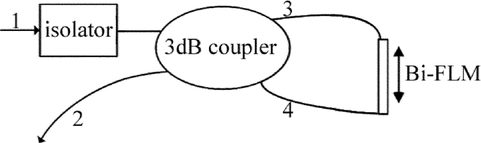
  • Bi-FLM传感器原理图如图 1所示。入射光从端口1经光隔离器进入3dB光纤耦合器,按1:1分成从端口3顺时针和端口4逆时针相向传输的两束光,最后汇聚在端口2,由于双折射光纤具有双折射效应,汇聚在端口2的两束光发生干涉。当双折射光纤受到应变时,导致双折射光纤双折射率和双折射光纤长度发生变化,从而导致干涉光谱随之改变,以此实现应变测量。

    Figure 1.  Schematic of Bi-FLM

    Bi-FLM传感器初始干涉光谱表达式为[10]

    式中,λ为干涉光谱波长,T(λ)为干涉光谱强度,相角θ=2πL0B0/λL0为光纤初始长度,B0为光纤初始双折射率。

    当双折射光纤受轴向应变后,相角变化量Δθ[10]

    式中,ΔL为双折射光纤轴向长度变化量,ΔB为光纤双折射率变化量。

    又因ΔB与轴向应变成正比[20],即:

    式中,εz=ΔL/L0=(L′-L0)/L0, 为双折射光纤轴向应变,单位为εL′为双折射光纤受应变后的长度; k是双折射应变系数,单位为1/ε,即光纤受1ε后双折射率变化大小。由(2)式、(3)式可得通过εz表示的Δθ表达式为:

    由(2)式、(3)式可得通过L′表示的Δθ表达式为:

    由(1)式、(4)式可得通过εz表示的受到轴向应变后的Bi-FLM干涉光谱表达式为:

    (6) 式是通过双折射光纤所受应变εz来描述干涉光谱T′(λ),与参考文献[1]、参考文献[4]、参考文献[10]中的一致,用于与下面推导的基于波长解调计算应变的理论表达式对比,以校验本文中推导的表达式正确性。

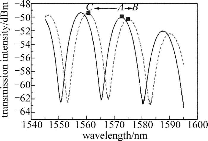
    由(6)式可知,随着应变的变化,干涉光谱也改变。作者曾通过实验得到Bi-FLM应变传感器0με时的波形,如图 2中实线所示[20],当传感光纤产生100με时,波形如图 2中虚线所示。基于传统波长解调的方法,无法自动确定A点是左移到B点,还是右移到C点,在人工测量时,可以根据经验或人为判断确定。根据(4)式,当相角变化Δθ超过2π时,信号周而复始,若实施计算机在线实时测量,则无从判断图中虚线是100με导致的相角变化Δθ产生的干涉光谱,还是更大的应变导致的相角变化2nπ+Δθ产生的干涉光谱(n为整数)。根据(6)式,干扰能改变初始相角θ导致干涉光谱平移,传统波长解调的方法无法区分是干扰改变初始相角还是外界传感量改变应变导致的干涉光谱变化。因此,基于传统波长解调的方法无法自动确定应变唯一大小,无法实现在线测量,容易受到外界干扰。以下推导基于波长解调计算应变的理论表达式,能根据干涉光谱任意4个相邻波谷波长相对位置蕴含着应变信息计算应变,无需人为判断,剔除了外界干扰,提高了测量精度。

    Figure 2.  Birefringence fiber loop mirror sensor wavelength demodulation

    由(1)式、(5)式可得通过L′表示的受到轴向应变后的干涉光谱表达式为:

    欲使(7)式对应干涉光谱T′(λ)的值最小,则:

    式中,n为整数,λn为整数n对应的波谷波长,其它依此类推。由(8)式解出:

    由(9)式可得:

    由(10)式可得:

    同理可得:

    由(11)式、(12)式可解出:

    由(12)式、(13)式可得:

    由(14)式可知,双折射光纤受轴向应变后的绝对长度L′可以由任意λn+1, λn, λn-1, λn-2这4个相邻的波谷波长、光纤初始长度L0、光纤初始双折射率B0和双折射应变系数k求出。将L′,L0代入εzL/L0=(L′-L0)/L0,可求出双折射光纤所受应变大小。也可以选择选择4个相邻的波峰波长计算应变,其理论推导过程与上面类似,不再赘述。

2.   分析与讨论
  • 为了验证(14)式的正确性,根据(6)式可得Bi-FLM应变传感器干涉波形,并通过编程找出干涉波形4个相邻波谷波长,将4个相邻波谷波长代入(14)式计算绝对长度L′,从而计算应变。选取2组不同波长范围的4个相邻波谷波长,两次计算的应变均与给定应变基本吻合。详细计算过程如下。

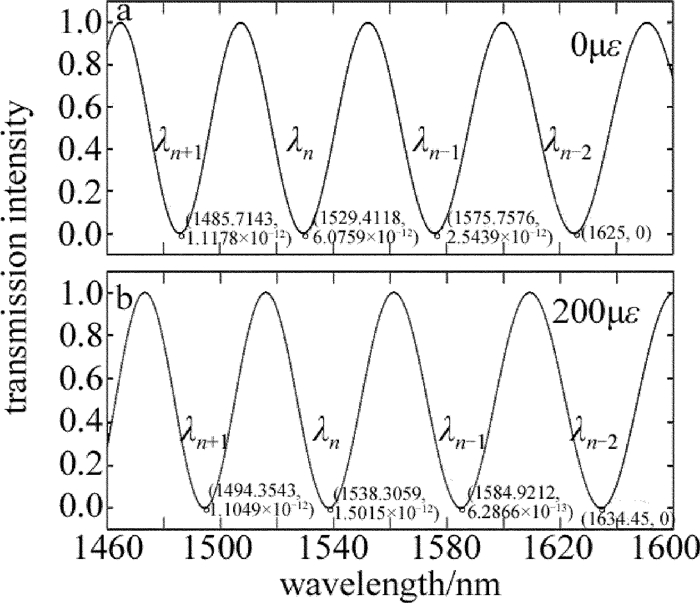
    双折射光纤长度L0=0.2m,双折射率B0=2.6×10⁻⁴,双折射应变系数k=7.3×0.001/ε,选取波长范围为典型通讯波长1550nm附近,横坐标λ的步长增量设置为0.0001nm,(6)式是描述干涉光谱T′(λ)与应变εz的关系表达式,根据(6)式可得各应变对应的干涉光谱T′(λ)。εz=0μεεz=200με时的干涉光谱如图 3所示。当εz为确定值时,干涉光谱强度T′(λ)是随λ变化的余弦函数,无量纲。

    Figure 3.  Birefringence fiber loop mirror sensor interference spectrum near 1550nm

    当传感光纤产生200με时,传统的基于波长解调的方法需要选定监测点,通过监测点波长的变化反推应变的大小。例如选择干涉光谱图 3a中的波谷λn为监测点,需要人为判断图 3a中的波谷λn是左移到图 3b中的λn+1的位置,还是右移到图 3b中的λn的位置,不利于实现计算机在线测量。且选择的监测点不同,同一Bi-FLM传感器灵敏度也各不相同,不利于传感器的校准。本文中推导的理论表达式只需要找出干涉光谱的任意λn+1, λn, λn-1, λn-2,4个相邻的波谷波长, 便可计算传感器应变大小。

    根据(9)式,当n值减小时,对应波谷波长增大,故λn+1 < λn < λn-1 < λn-2,如图 3所示。找出图中干涉光谱的4个连续波谷的坐标,εz=200με时,4个连续波谷波长λn+1, λn, λn-1, λn-2依次为1494.3543nm,1538.3059nm,1584.9212nm,1634.4500nm,将4个连续波谷波长、光纤初始长度L0=0.2m、光纤初始双折射率B0=2.6×10⁻⁴和双折射应变系数k=7.3×0.001/ε代入(14)式,计算可得双折射光纤的绝对长度L′=0.200039978870329m,将L′代入εzL/L0=(L′-L0)/L0,计算得应变εz=199.894351642776με。其它应变的计算以此类推,表 1中为计算结果。

    given strain/με λn-2/nm λn-1/nm λn/nm λn+1/nm calculated strain /με
    100 1629.725 1580.3394 1533.8588 1490.0343 99.5752477940537
    200 1634.45 1584.9212 1538.3059 1494.3543 199.894351642776
    300 1639.175 1589.503 1542.7529 1498.6743 298.913752005692
    400 1643.9 1594.0848 1547.2 1502.9943 399.232867617089
    500 1648.625 1598.6667 1551.6471 1507.3143 500.740355994095
    600 1653.35 1603.2485 1556.0941 1511.6343 599.759737768407
    700 1658.075 1607.8303 1560.5412 1515.9543 700.078840896179
    800 1662.8 1612.4121 1564.9882 1520.2743 799.098235643586
    900 1667.525 1616.9939 1569.4353 1524.5943 899.417350395254

    Table 1.  Calculating strain results by four adjacent wave valley wavelengths near 1550nm

    表 1可以看出,通过本文中推导的理论表达式计算的应变与给定应变基本吻合,但仍存在一定误差,误差是由于(6)式绘制的Bi-FLM干涉光谱波形横坐标λ的步长增量设置为0.0001nm,而非连续步长,导致图 3中某些波谷的纵坐标不完全等于0,而是近似为0,该点不是严格意义上的波谷点,因此计算的4个连续波谷波长λn+1, λn, λn-1, λn-2也是近似接近理论值,从而与给定应变存在一定误差。

    为了验证(14)式计算应变大小可以由任意λn+1, λn, λn-1, λn-2 这4个相邻的波谷波长计算得到,本文中选取另一典型通讯波长1300nm附近的4个相邻波谷波长进行计算,εz=200με时的干涉光谱如图 4所示,计算方法同上。各应变计算结果如表 2所示。虽然选取的4个相邻的波谷波长与表 1不同,但计算的应变与给定应变仍基本吻合,因此, 基于(14)式计算应变大小可以由任意4个相邻波谷波长λn+1, λn, λn-1, λn-2进行计算。

    Figure 4.  Birefringence fiber loop mirror sensor interference spectrum near 1300nm

    given strain/με λn-2/nm λn-1/nm λn/nm λn+1/nm calculated strain /με
    100 1337.2103 1303.78 1271.9805 1241.6952 100.267973850571
    200 1341.0872 1307.56 1275.6683 1245.2952 200.632670522283
    300 1344.9641 1311.34 1279.3561 1248.8952 300.997382638585
    400 1348.841 1315.12 1283.0439 1252.4952 401.362110053483
    500 1352.7179 1318.9 1286.7317 1256.0952 501.726852655537
    600 1356.5949 1322.68 1290.4195 1259.6952 600.029301964372
    700 1360.4718 1326.46 1294.1073 1263.2952 700.394017769113
    800 1364.3487 1330.24 1297.7951 1266.8952 800.758748691899
    900 1368.2256 1334.02 1301.4829 1270.4952 901.123494590345

    Table 2.  Calculating strain results by four adjacent wave valley wavelengths near 1300nm

    根据表 2中计算的各应变对应的波谷波长λn+1, λn, λn-1, λn-2,传统的基于波长解调的方法分别选定波长极小值λn+1和波长极大值λn-2为监测点,得到的应变与波长拟合直线如图 5所示。以λn+1λn-2为监测点的传感器灵敏度分别0.036nm/με,0.03877nm/με。选定的监测点不同,Bi-FLM传感器的灵敏度也不同,导致同一传感器灵敏度大小不一致,不利于传感器的校准。本文中推导的理论表达式任意选定的4个相邻的波谷波长λn+1, λn, λn-1, λn-2不影响计算应变的大小,无需校准。计算应变时无需人为判断,有助于实现计算机在线测量。干扰只是改变初始相角导致干涉光谱简单平移,但外界传感量改变应变,导致干涉光谱任意4个相邻波谷波长的相对位置发生变化,并以此计算应变,能剔除外界干扰,提高测量精度。

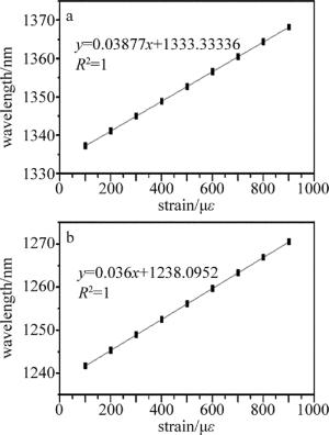
    Figure 5.  Relationship between strain and wavelength

3.   结论
  • 本文中选取了典型通讯波长1550nm和1310nm附近4个相邻的波谷波长,通过本文中推导的理论表达式计算Bi-FLM传感器受轴向应变后的双折射光纤绝对长度,并以此计算所受应变大小。通过两种不同波长范围计算的传感器应变大小一致,克服了传统的基于波长解调方法因监测点不同导致同一传感器灵敏度各异、不利于传感器校准的缺点。计算应变时无需人为判断,克服了传统的基于波长解调方法无法自动确定传感量唯一大小、不利于计算机在线测量的缺点。根据干涉光谱任意4个相邻波谷波长相对位置蕴含着应变信息,能区分是干扰改变初始相角还是外界传感量改变应变导致的干涉光谱变化,能剔除外界干扰,提高测量精度。本文中研究结果对Bi-FLM应变、振动等各类传感器实现计算机在线测量,提高测量精度具有指导意义。但本文中的测量方法需要连续4个相邻的波谷波长,需要的信息量较多,在一定的光源波长范围内,仅有较短的传感光纤的双折射光纤环镜传感器没有足够的波谷点,因此,有待进一步研究一种需要信息量较少的在线测量方法。

Reference (20)

Catalog

    /

    DownLoad:  Full-Size Img  PowerPoint
    Return
    Return