Advanced Search

ISSN1001-3806 CN51-1125/TN Map

Volume 44 Issue 3
Jul.  2020
Article Contents
Turn off MathJax

Citation:

Effect of laser parameters on slit morphology and roughness of vascular stents

  • Corresponding author: ZHANG Haiyun, zhy@sdut.edu.cn
  • Received Date: 2019-08-16
    Accepted Date: 2019-09-18
  • In order to study the effect of laser processing parameters on the slit morphology and surface roughness of vascular stent, the experiment of optical fiber laser cutting of cardiovascular stent 316L was carried out by means of comparative analysis of different parameters. The effects of different process parameters such as laser pulse width, laser power, and cutting speed on the slit morphology and roughness of the material were analyzed, and the optimum combination of process parameters for laser cutting support was obtained. The results show that there are differences in slit morphology and surface roughness in different regions, in which the thickness of the vaporization zone is mainly affected by the pulse width and laser power. When the pulse width is 35μs, the maximum thickness of the slit vaporization zone can reach 120μm. In addition, the roughness of the slit vaporization zone of the support decreases at first and then increases with the increase of the cutting speed. When the cutting speed is 6mm/s, the lowest value of slit surface roughness is 650nm. The results lay a theoretical foundation for the research and subsequent finishing of cardiovascular stent optical fiber.
  • 加载中
  • [1]

    MA J L, YU Zh H, ZHU M, et al. Review on the property of NiTi vascular stent[J]. Metallic Functional Materials, 2015, 22(2): 56-59(in Chinese).
    [2]

    LIU L, LI D B, TONG Y F, et al. Laser processing technology and its research progress of vascular stent[J]. Hot Working Technology, 2017, 46(5): 15-18(in Chinese).
    [3]

    LU L B, WANG H P, GUAN Y Ch, et al. Laser microfabrication of biomedical devices[J]. Chinese Journal of Lasers, 2017, 44(1): 0102005(in Chinese). doi: 10.3788/CJL201744.0102005
    [4]

    ZHANG J Y, ZHANG H Y, LI Zh Y, et al. Effect of laser parameters on recasting layer and heat affected zone of cardiovascular stents[J]. Laser Technology, 2019, 43(4): 460-463(in Chinese).
    [5]

    GUAN B G, MENG H Y, LIAO J H, et al. Fabrication and influence factors of mental cardiovascular stent[J]. Acta Laser Biology Sinica, 2011, 20(2): 274-279 (in Chinese).
    [6]

    ZHANG Ch, WANG G, YANG Zh G, et al. Optimization of techno-logy parameters for fracture splitting grooves of connecting rods fabricated by pulse fiber laser[J]. Laser Technology, 2018, 42(3):422-426 (in Chinese).
    [7]

    SUN J F, ZHANG Q M, YANG Zh, et al. Research on optimization of fiber laser cutting technology of 316L stainless steel[J]. Applied Laser, 2016, 36(1): 72-77(in Chinese).
    [8]

    YAO L, WU N, HAN X J, et al. Fiber laser cutting and its application prospects in precision machining[J]. Hot Working Technology, 2018, 47(7): 11-15(in Chinese).
    [9]

    LI T Q, MAO X J, LEI J, et al. Analysis and comparison of solid-state lasers and fiber lasers on the coupling of rod-type photonic crystal fiber[J]. Chinese Optics, 2018, 11(6): 958-973(in Chinese). doi: 10.3788/co.20181106.0958
    [10]

    PFEIFER R, HERZOG D, HUSTEDT M, et al.Pulsed Nd:YAG laser cutting of NiTi shape memory alloys-influence of process parameters[J]. Journal of Materials Processing Technology, 2010, 210(14): 1918-1925. doi: 10.1016/j.jmatprotec.2010.07.004
    [11]

    ZHANG X B. Laser drilling with 100ns~700ns YAG laser in Nickel-based alloy[J]. Applied Laser, 2005, 25(2):90-92 (in Chin-ese).
    [12]

    MENG H Y, LIAO J H, GUAN B G, et al. Fiber laser cutting technology on coronary artery stent[J]. Chinese Journal of Lasers, 2007, 34(5): 733-736(in Chinese).
    [13]

    LI Q, SUN G F, LU Z, et al. Experimental research on fiber laser underwater cutting of 1mm thick 304 stainless steel[J]. Chinese Journal of Lasers, 2016, 43(6):0602001(in Chinese). doi: 10.3788/CJL201643.0602001
    [14]

    MEIJER J, DU K, GILLNER A, et al. Laser machining by short and ultrashort pulses state of the art and new opportunities in the age of the photons[J]. CIRP Annals Manufacturing Technology, 2002, 51(2): 531-550. doi: 10.1016/S0007-8506(07)61699-0
    [15]

    MA Zh J, REN C, YAN B, et al. Preparation and creation of the composite of 316L stainless steel and CaSiO3 for bone repairing implantation[J]. Nonferrous Metal Materials and Engineering, 2018, 39(1):31-37(in Chinese).
    [16]

    LI W B. Research on femtosecond laser purse polishing of silicon carbide ceramic material[D]. Harbin: Harbin Institute of Technology, 2011: 15-45(in Chinese).
    [17]

    ZHANG T Z. Study on the mechanism of melt ejection, recast layer and micro crack formation in millisecond laser drilling[D]. Nanjing: Nanjing University of Science & Technology, 2017: 17-47(in Chinese).
    [18]

    TAN Ch, SUN X Y, YIN K, et al. Surface roughness of cutting metal by femtosecond laser[J]. Journal of Central South University (Science and Technology Edition), 2015, 46(12): 4481-4487 (in Chinese).
    [19]

    LI Zh, WANG T, LIU J, et al. Effect of process parameters on co-rrosion resistance of aluminum alloy hybrid welded joints[J]. Laser Technology, 2019, 43(2): 189-194 (in Chinese).
    [20]

    MANLEY J, HOUSH R, WAGNER F, et al. Water-guided lasers create clean cuts[J]. Laser Focus World, 2004, 40(5):15-18.
  • 加载中
通讯作者: 陈斌, bchen63@163.com
  • 1. 

    沈阳化工大学材料科学与工程学院 沈阳 110142

  1. 本站搜索
  2. 百度学术搜索
  3. 万方数据库搜索
  4. CNKI搜索

Figures(7) / Tables(1)

Article views(6365) PDF downloads(16) Cited by()

Proportional views

Effect of laser parameters on slit morphology and roughness of vascular stents

    Corresponding author: ZHANG Haiyun, zhy@sdut.edu.cn
  • School of Mechanical Engineering, Shandong University of Technology, Zibo 255049, China

Abstract: In order to study the effect of laser processing parameters on the slit morphology and surface roughness of vascular stent, the experiment of optical fiber laser cutting of cardiovascular stent 316L was carried out by means of comparative analysis of different parameters. The effects of different process parameters such as laser pulse width, laser power, and cutting speed on the slit morphology and roughness of the material were analyzed, and the optimum combination of process parameters for laser cutting support was obtained. The results show that there are differences in slit morphology and surface roughness in different regions, in which the thickness of the vaporization zone is mainly affected by the pulse width and laser power. When the pulse width is 35μs, the maximum thickness of the slit vaporization zone can reach 120μm. In addition, the roughness of the slit vaporization zone of the support decreases at first and then increases with the increase of the cutting speed. When the cutting speed is 6mm/s, the lowest value of slit surface roughness is 650nm. The results lay a theoretical foundation for the research and subsequent finishing of cardiovascular stent optical fiber.

0.   引言
  • 目前,心血管疾病已成为威胁我国国民健康的“第一杀手”,其发病率和死亡率远远高于肿瘤,而且一直处于上升趋势,日益成为我国社会经济的重大负担。据报告,我国是心血管疾病大国,心血管病患病人数已达2.9亿。治疗心血管疾病主要方法是心脏介入术,具有良好的治疗效果,恢复周期短[1-3]。心脏介入术的主要治疗手段就是植入心血管支架,根据输送方式划分,主要有自膨胀性支架与球囊膨胀性支架两种。目前球囊式支架加工方式主要采用激光切割工艺,具有生产效率高、质量可靠和范围广泛的特点[4-5]。但是由于激光切割属于热加工,所以可能导致切缝不同位置处的表面形貌和表面质量存在差异,进而影响支架的刚度、强度和使用寿命。通过国内外诸多学者对激光切割后不同位置的表面形貌和表面质量的研究,可知影响心血管支架切缝形貌、粗糙度以及变化趋势的主要因素有:切割速率、脉冲宽度和脉冲功率等[6-8]。光纤激光是20世纪80年代开始发展新加工工艺方法,因其具有加工精度高、光束质量好和加工效率高的特点,开始应用于心血管支架的加工[9-12]

    为了研究不同光纤激光加工工艺参量对心血管支架切缝表面形貌及粗糙度形成机理及变化规律,本文中从光纤激光切割的不同区域着手,分析在不同的工艺参量下切缝的表面形貌和粗糙度的形成机理以及变化趋势,方便后续的心血管支架方向的光整加工。

1.   实验方法与设备
  • 本实验中采用的型号为TLS-HT1100的激光切割设备,实验的激光参量可调范围如表 1所示。

    process parameters laser power/W pulse width/μs pulse frequency/Hz cutting speed/
    (mm·s-1)
    adjustable range 0~200 1~100 1~10000 0~10
    actual range 100~150 10~35 7000~10000 3~8

    Table 1.  The range of laser process parameters

    其中,该激光切割机的加工范围为0mm~100mm,光纤激光器波长为(1064±10)nm,光束质量因子M2 < 1.1,最小切割峰宽15μm,光斑聚焦直径为20μm。激光切割机兼容干切和湿切两种工艺,整机为密封性设计,配合防水飞溅模块激光,切割头自动对焦,无需多次地调整焦距。心血管支架材料为316L,原材料管厚为0.15mm,外径为2mm,切割后长度为13mm。切割过程中,工件相对于光束的运动主要通过工控机控制x轴平移和y轴转动实现[13-15]

  • 采用本实验室的扫描电子显微镜(型号为Quanta 250)和白光干涉仪(型号为VS1800)对切割后的心血管支架的表面形貌及粗糙度进行检测,用扫描电子显微镜观测血管支架的切缝宽度、变形、裂纹和损伤状况等。

2.   实验结果及讨论
  • 本实验中采用激光功率实际可调范围为100W~150W,根据计算公式[16-18]可以得到最小激光功率密度为:

    式中, P为激光功率;r为光斑半径;W为激光功率密度。

    根据(1)式计算得到的最小激光功率密度已经超过汽化切割最小值,所以本实验中采用汽化切割方式[19-20]。但在实际切割加工过程中,由于加工工艺参量的变化使光斑的激光功率密度在支架切缝不同区域呈现差异性,因此, 激光切割后的支架切缝形貌在不同区域呈现不同的特点,按照其特点分为汽化区、熔化区和熔渣区,如图 1所示。在激光切割过程中,由于支架切缝上端最先与光斑接触,上端的激光光斑功率密度最大,汽化区就会在管材的上端形成。当光斑传递到管材中部时,由于光斑穿过汽化区,造成能量损失,导致光斑的激光功率密度减小,光斑剩余的能量能熔化切缝中部的材料,所以切缝中部为熔化区。在光斑到达切缝最下端时,由于绝大部分的能量被汽化区和熔化区吸收,管材下端主要是辅助气体和剩余能量作用形成,去除的材料与内表面直接接触形成熔渣区。

    Figure 1.  Slit morphology distribution map

  • 为了研究脉冲宽度对切缝形貌及粗糙度的影响,根据已有研究数据,选定在脉冲频率7000Hz、切割速率为7mm/s的参量下进行切割实验。不同脉冲宽度下支架切缝各区域厚度分布变化规律如图 2a所示。支架汽化区和熔化区的厚度随着脉冲宽度的增大而增大,熔渣区随着脉冲宽度增大而减小。从支架切缝汽化区的变化来看,随着汽化区域的脉冲宽度与激光占空比的增大,光斑传递的能量随之逐渐增多,能量的传递使管材的汽化切割部分扩大,汽化区的厚度变化较大;另一方面, 当脉冲宽度增大时,激光的峰值功率密度会随之减小,光斑在管材传递能量的速率和效率变慢,随着切缝增深所造成的能量损失会逐渐增加,因此支架熔化区变化平缓。当脉冲宽度在15μs~35μs之间变化时,支架汽化区的厚度变化范围为60μm~120μm,支架熔化区的厚度变化范围为80μm~90μm。图 2b为脉冲宽度15μs时扫描电子显微镜(scanning electron microscope,SEM)拍摄的切缝表面形貌分布情况。

    Figure 2.  Slit thickness distribution and 15μs surface topography in different regions with different pulse width a—thickness distribution map b—15μs slit surface morphology

    不同脉冲宽度支架切缝区域表面粗糙度Ra值的变化如图 3所示。随着脉冲宽度的不断增加,支架切缝的汽化区表面粗糙度Ra值始终低于切缝熔化区和熔渣区的Ra值,汽化区的表面质量最优,熔化区次之,熔渣区的表面质量最差。当切缝支架的脉冲宽度为15μs时,汽化区的光斑的能量密度较小而峰值功率密较大,造成切缝区域光斑的光照强度较弱,所以汽化区的Ra值较小; 当支架切缝的脉冲宽度为25μs时,光斑能量密度增大,峰值功率降低,激光占空比不断变大,光斑能量作用于支架切缝汽化区和熔化区的时间增长,造成支架切缝的汽化区与熔化区Ra值会逐渐增大,支架汽化区Ra值达到了最大值1100nm; 当脉冲宽度继续增加时,激光占空比与光斑的激光峰值功率密度等因素,使汽化区的光斑能量较少,而熔化区与熔渣区的光斑能量较多,从而造成支架汽化区Ra值会减小,熔化区与熔渣区Ra值会增大。

    Figure 3.  Variation diagram of Ra value in slotted regions with different pulse width

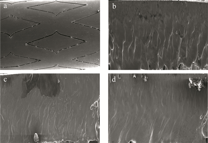
  • 为了研究激光功率对切缝形貌及粗糙度的关系,选用脉冲宽度15μs、切割速率7.5mm/s的工艺参量下进行切割实验,得到了不同激光功率支架切缝形貌的变化图,如图 4所示。图 4a是激光功率100W得到的支架切缝形貌图。由于光斑的功率密度和能量密度较低,导致光斑无法切透管材底部。当激光功率不断增加到110W时,如图 4b所示。此时管材完全被切透,但切缝内部的光斑能量依然很少,辅助气体吹除是影响切缝形成的关键,导致支架切缝表面起伏较大且呈现涟漪状结构。激光功率持续增加,光斑的能量密度也增加,导致光斑的轴向能量传递效率加快,光斑径向传递的能量和传递速率减少,光斑的稳定性越来越好,切缝表面涟漪状结构减少。激光功率为130W时,支架切缝表面涟漪状结构明显减少,如图 4c所示。激光功率达到150W时,支架切缝表面平稳且不存在涟漪状结构,如图 4d所示。

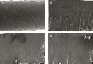
    Figure 4.  Surface topography of slit with different laser power a—P=100W b—P=110W c—P=130W d—P=150W

    不同激光功率下支架切缝区域分布变化规律如图 5a所示。激光功率小于110W时,由于光斑的能量密度低,光斑的光照强度弱,激光不能切透支架管材。随着激光功率的增加,光斑的能量密度和占空比随之增加,光斑的沿切缝方向的传递速度和速率增加,汽化区和熔化区厚度增加。当激光功率为110W~150W之间变化时,支架汽化区的变化范围为10μm~100μm,熔化区变化范围为50μm~70μm。不同激光功率切缝各区域Ra值的变化情况如图 5b所示。可以看出, 支架汽化区的Ra值一直处于最低水平,熔化区的Ra值总体变化范围最小。当激光功率在110W~140W变化时,光斑的激光功率密度是影响支架切缝各区域Ra的主要因素,激光功率增加,汽化区吸收的光斑能量持续增加,因此切缝汽化区Ra值不断增加,反之切缝熔化区和熔渣区变化缓慢。当激光功率超过140W时,光斑的峰值功率密度是影响各区域Ra值的主要因素,激光功率增加,光斑的峰值功率密度增加,但能量在汽化区的时间减少,光照强度随之减弱,所以切缝汽化区Ra值急剧下降。

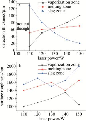
    Figure 5.  Thickness distribution and roughness variation of slit regions with different laser power a—thickness distribution map b—variation diagram of Ra value

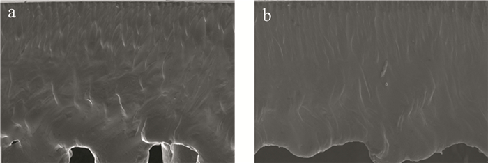
  • 为了研究切割速率对切缝形貌及粗糙度的关系,选用脉冲宽度15μs、脉冲频率7000Hz的工艺参量下进行切割实验,得到了不同切割速度下支架切缝形貌的变化图。图 6a图 6b分别是切割速率为3mm/s和7mm/s下切缝的表面形貌图。可以看出,切割速率为3mm/s时,由于切割速率较慢,光斑与支架接触时间较长,材料吸收的能量较多,材料流动性能力加强,导致支架切缝表面不均匀,存在许多凹坑。随着切割速度不断增加,光斑与支架的接触时间变短,材料吸收的光斑能量也减少,材料流动性减弱,支架切缝表面趋于平稳。

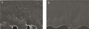
    Figure 6.  Surface topography of support slit under different cutting speed a—v=3mm/s b—v=7mm/s

    不同切割速率下切缝的变化如图 7a所示。当切割速率在3mm/s~6mm/s时,支架的汽化区厚度随切割速度增大持续降低; 切割速率在6mm/s~8mm/s时,切缝汽化区厚度随切割速率增大而降低。这是因为切割速率小于6mm/s时,切割速率增加导致支架单位面积吸收的能量减少,管材吸收的总能量随之减少,因而切缝汽化区厚度减小;切割速率大于6mm/s时,光斑传递到管材的能量大部分集中在汽化区,导致汽化区的厚度逐渐增加。切割速率与切缝各区域粗糙度的关系如图 7b所示。可以看出,不同区域的粗糙度随着切割速率的变化起伏比较大,主要由于切割速率增大时,管材的熔融时间较短,气体的吹除时间也较短,支架切缝总体的粗糙度随切割速率先减少后增加。当切割速率为6mm/s时,支架切缝各区域的Ra值最低,支架汽化区Ra=650nm。因为支架切缝表面粗糙度随切割速率的变化起伏最大,所以在研究各工艺因素时,应该优先将切割速率放在首位。

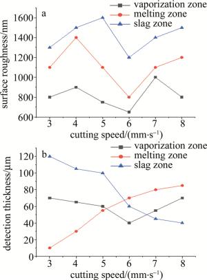
    Figure 7.  Thickness distribution map and roughness variation diagram of slit area with different cutting speed a—thickness distribution map b—variation graph of Ra value

3.   结论
  • 研究了不同加工工艺参量下心血管支架切割过程中切缝各区域表面形貌及粗糙度变化趋势和产生的机理。

    (1) 支架切缝按照其表面形貌特点分为汽化区、熔化区和熔渣区。支架切缝汽化区厚度主要受脉冲宽度和激光功率的影响,与脉冲宽度和激光功率成正比。当脉冲宽度为15μs~35μs时,汽化区的厚度变化范围为60μm~120μm;当激光功率为110W~150W时,汽化区的厚度变化范围为10μm~100μm。支架切缝熔化区主要受切割速率的影响,在脉冲频率和激光功率下变化不明显,随切割速率增加先增大后减小。当切割速率为3mm/s~8mm/s时,汽化区厚度变化范围为40μm~70μm; 当切割速率为6mm/s,汽化区最小厚度为40μm。

    (2) 支架切缝各区域的表面粗糙度分布不均匀,各区域相差较大。总体来看,随着脉冲宽度、激光功率和切割速度逐渐增加,汽化区的支架切缝表面质量达到最好,而熔渣区的支架切缝表面质量与之相反。另一方面,切割速率是影响支架切缝3个区域表面粗糙度的主要因素,切缝汽化区随脉冲宽度和激光功率增加先增大后减小。当脉冲宽度为25μs时,切缝汽化区的Ra值最高为1100nm;为当切割速率为6mm/s时,支架切缝Ra值最低为650nm。

Reference (20)

Catalog

    /

    DownLoad:  Full-Size Img  PowerPoint
    Return
    Return