Advanced Search

ISSN1001-3806 CN51-1125/TN Map

Volume 44 Issue 3
Jul.  2020
Article Contents
Turn off MathJax

Citation:

Research on orthogonal vision and inclinometer combination spatial pose measurement method

  • Corresponding author: MA Guolu, maguolu999@163.com
  • Received Date: 2019-07-05
    Accepted Date: 2019-07-12
  • To solve the measurement and recognition contradiction between macro-scale and micro-feature of trans-scale miniature parts in precision assembly, a high-precision pose measurement system based on orthogonal binocular vision and inclinometer combination was proposed. The system built the coordinate transformation relationship among imaging unit, auxiliary measurement unit of inclinometer, and clamping unit of parts. An analytical algorithm for high-precision measurement of pose measurement of miniature parts based on the coordination transformation and angle measured by inclinometer was introduced. In experiment, fiber array and jumper were the research object, afterwards spatial pose constantly measurement and automatic assembly experimental platform was built. The results show that position and attitude deviation measured by the combined measurement system are less than (±2μm, ±2μm, ±3μm) and (±0.005°, ±0.004°, ±0.005°), respectively, in the field of 3mm×2mm×2mm. Compared with the traditional measurement methods, the system improves the measurement accuracy of the miniature parts significantly. This method can further satisfy the requirements of pose precision measurement and automatic assembly of miniature parts.
  • 加载中
  • [1]

    WANG C, WANG Q, DONG R F, et al. Dynamic self-assembly of micro-nanomotor[J]. Inorganic Chemistry Communications, 2018, 91(5):8-15.
    [2]

    COOK R C, KOZIOZIEMSKI B J, NIKROO A, et al. National ignition facility target design and fabrication[J]. Laser and Particle Beams, 2008, 26(3): 479-487. doi: 10.1017/S0263034608000499
    [3]

    LOBO J, DIAS J. Relative pose calibration between visual and inertial sensors[J]. The International Journal of Robotics Research, 2007, 26(6): 561-575. doi: 10.1177/0278364907079276
    [4]

    HUANG Zh H, ZHANG Y N, FANG Sh, et al. Method of object pose measurement based on single PSD[J]. Acta Photonica Sinica, 2018, 47(9): 0904001(in Chinese). doi: 10.3788/gzxb20184709.0904001
    [5]

    POPA D O, STEPHANOU H E. Micro and mesoscale robotic assembly[J]. Journal of Manufacturing Processes, 2004, 6(1): 52-71.
    [6]

    WANG H Y, DUAN F J, JIANG J J, et al. A two-dimensional photoelectric level inclination measuring system[J]. Optics and Precision Engineering, 2017, 25(12): 3120-3127(in Chinese). doi: 10.3788/OPE.20172512.3120
    [7]

    MA G L, LIU L X, ZHAO B. Measurement and automatic calibration of spatial incident angle based on non-diffracting beam[J]. Chinese Journal of Scientific Instrument, 2016, 37(8): 1906-1912(in Chin-ese).
    [8]

    WANG F B, LIU Y, CHENG Y, et al. Six-DOF attitude transform visual experiment platform and its application[J]. Laser Technology, 2018, 42(6):751-757(in Chinese).
    [9]

    ZHOU C C, LI X H. Measuring system of thread parameters based on machine vision[J]. Laser Technology, 2016, 40(5): 643-647(in Chinese).
    [10]

    TANG Y L, ZHANG Zh J, ZHAO X F, et al. Design of precise alignment orthogonal system used in micro-assembly[J]. Optics and Precision Engineering, 2012, 20(7): 1542-1550(in Chinese). doi: 10.3788/OPE.20122007.1542
    [11]

    LIAO Q, LUO J, XIE Q T. Analysis of precision measurement system based on active vision[J]. Journal of Chongqing University of Technology (Naltural Science Edition), 2010, 24(4): 79-85(in Chinese).
    [12]

    LOU Zh F, WANG X D, YOU B, et al. Pressing-fitting technology and instrument for precision small parts[J]. Optics and Precision Engineering, 2015, 23(6): 1605-1611(in Chinese). doi: 10.3788/OPE.20152306.1605
    [13]

    ZOU Y, RONG W B, XING J Y, et al. An auto-docking assembly test system for target suits[J]. Robot, 2016, 38(1): 115-121(in Chinese).
    [14]

    HE F Y, GAO Y, ZHU J G, et al. Optimized pose measurement system combining monocular vision with inclinometer sensors[J]. Acta Optica Sinica, 2016, 36(12): 1215002(in Chinese). doi: 10.3788/AOS201636.1215002
    [15]

    ZHU J G, YU Zh J. The principle of vision metrology[M]. Beijing: China Machine Press, 2011:16-30(in Chinese).
    [16]

    REN B Y, CHAI L R, WEI K, et al. A method for measuring 3-D pose of assembly end of long shaft part using orthogonal binocular stereovision[J]. Journal of Harbin Institute of Technology, 2017, 49(1): 60-65(in Chinese).
  • 加载中
通讯作者: 陈斌, bchen63@163.com
  • 1. 

    沈阳化工大学材料科学与工程学院 沈阳 110142

  1. 本站搜索
  2. 百度学术搜索
  3. 万方数据库搜索
  4. CNKI搜索

Figures(4) / Tables(1)

Article views(7951) PDF downloads(17) Cited by()

Proportional views

Research on orthogonal vision and inclinometer combination spatial pose measurement method

    Corresponding author: MA Guolu, maguolu999@163.com
  • Ministry of Education Key Laboratory of Testing Technology for Manufacturing Process, Southwest University of Science and Technology, Mianyang 621000, China

Abstract: To solve the measurement and recognition contradiction between macro-scale and micro-feature of trans-scale miniature parts in precision assembly, a high-precision pose measurement system based on orthogonal binocular vision and inclinometer combination was proposed. The system built the coordinate transformation relationship among imaging unit, auxiliary measurement unit of inclinometer, and clamping unit of parts. An analytical algorithm for high-precision measurement of pose measurement of miniature parts based on the coordination transformation and angle measured by inclinometer was introduced. In experiment, fiber array and jumper were the research object, afterwards spatial pose constantly measurement and automatic assembly experimental platform was built. The results show that position and attitude deviation measured by the combined measurement system are less than (±2μm, ±2μm, ±3μm) and (±0.005°, ±0.004°, ±0.005°), respectively, in the field of 3mm×2mm×2mm. Compared with the traditional measurement methods, the system improves the measurement accuracy of the miniature parts significantly. This method can further satisfy the requirements of pose precision measurement and automatic assembly of miniature parts.

0.   引言
  • 微装配技术广泛应用于民用、国防微制造等领域[1-2],其装配质量直接由测量精度决定。当前微小型零件的位姿测量方式多样,但在测量过程中仍存在诸多问题[3-4],譬如微小型零件尺寸跨度大,一般的测量方法无法同时兼顾宏尺度、微特征两者之间的分辨矛盾[5-6];微小型零件常因空间阻隔、遮挡,造成关键尺寸无法直接测量,不能满足空间位姿测量的要求;微小型零件的装配误差尺度小,而装配过程中需考虑系统累积误差的影响,因此微装配系统对微小型零件的位姿测量提出了更高的要求[7]

    当前,机器视觉广泛应用于微小型零件的位姿测量[8-9],常有如下几种测量方式:第1种是正交光学对准检测[10],其测量原理是单目视觉结合直角棱镜的反射特性,可同时获取待装配零件与基体零件的图像信息,从而实现跨尺度零件的位姿测量, 但该测量方式仅适用于形式单一的平板类零件,而对于有深度测量要求的零件则不能满足测量需求; 第2种是主动视觉扫描测量[11],其测量原理是控制相机移动扫描微小型零件,并将扫描图片进行重建,进而实现全局特征的测量,但对于具有复杂轮廓的零件,该测量方式求解效率较低,运算复杂; 第3种是多维视觉与力/位移传感器的组合测量[12-13],其测量原理是视觉成像系统对零件进行多视角成像,而对于检测盲点,则需通过力/位移传感器进行监测,但该方式在测量过程中将会引入接触应力,极易造成易碎零件表面划伤,不能满足无损装配要求。

    针对上述问题,本文中提出了基于正交双目视觉与倾角仪组合测量位姿的解析算法。基于正交双目视觉的测量原理,求解出特征点的空间坐标;结合倾角仪提供的角度信息,构建了空间位姿测量模型;同时,搭建了组合测量系统的实验平台,验证了测量系统的精度与可靠性,为微小型零件的空间位姿精密测量与自动装配提供新的参考方法。

1.   正交双目视觉与倾角仪组合的相对位姿测量
  • 组合系统的测量原理如图 1所示。在两夹具上边缘标记特征点,并在其下方各固定一个倾角仪,通过正交双目视觉求解的位姿信息再结合倾角仪提供角度信息,即可求得两夹具的相对位姿关系,同时也间接实现了待装配零件与基体零件相对位姿的测量。如图 1所示,组合测量系统共有6个坐标系:成像坐标系Ⅰ为O1x1y1z1,世界坐标系Owxwywzw的原点与O1重合且无旋转,成像坐标系Ⅱ为O2x2y2z2,夹具坐标系Ⅰ为Otxtytzt,夹具坐标系Ⅱ为Omxmymzm,倾角仪坐标系Ⅰ为Oq, 1xq, 1yq, 1zq, 1,倾角仪坐标系Ⅱ为Oq, 2xq, 2yq, 2zq, 2。由于倾角仪无定位识别功能,只为组合测量系统提供角度信息,则相应的平移矩阵不需考虑,因此可将倾角仪坐标系的原点设置在夹具坐标系的原点。由前期标定可知成像坐标系Ⅰ与成像坐标系Ⅱ、夹具坐标系Ⅰ与倾角仪坐标系Ⅰ、夹具坐标系Ⅱ与倾角仪坐标系Ⅱ的关系。

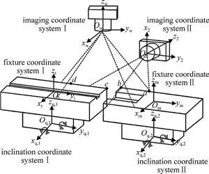
    Figure 1.  Schematic diagram of combined measurement system

    图 1中坐标系的转换关系如下:夹具坐标系Ⅱ到夹具坐标系Ⅰ的旋转、平移矩阵为Rm, t, Tm, t; 夹具坐标系Ⅱ到倾角仪坐标系Ⅱ的旋转矩阵为Rm, q, 2; 夹具坐标系Ⅱ到世界坐标系的旋转平移矩阵为Rm, w, Tm, w; 倾角仪坐标系Ⅱ到世界坐标系的旋转、平移矩阵为Rq, 2, w, Tq, 2, w; 成像坐标系Ⅱ到世界坐标系的旋转、平移矩阵为R2, w, T2, w; Rm, t对应绕xt, yt, zt轴的旋转角为αm, t, βm, t, γm, t; Rm, q, 2对应绕xq, 2, yq, 2, zq, 2轴的旋转角为αm, q, 2, βm, q, 2, γm, q, 2; Rm, w对应绕xw, yw, zw轴的旋转角为αm, w, βm, w, γm, w; Rq, 2, w对应绕xw, yw, zw轴的旋转角为αq, 2, w, βq, 2, w, γq, 2, w; R2, w对应绕xw, yw, zw轴的旋转角为α2, w, β2, w, γ2, w; 倾角仪Ⅱ的xq, 2, yq, 2轴输出的角度为ϕ2, θ2。夹具坐标系Ⅰ与成像坐标系、倾角仪Ⅰ坐标系转换关系类似,不再赘述。

    由夹具坐标系Ⅱ、世界坐标系、夹具坐标系Ⅰ的转换关系可知:

    式中,Tm, t=[Tm, t, x Tm, t, y Tm, t, z]T, Tt, w=[Tt, w, x Tt, w, y Tt, w, z]T, Tm, w=[Tm, w, x Tm, w, y Tm, w, z]TTm, t, x, Tm, t, y, Tm, t, zOmxmymzm沿Otxtytztx, y, z向的平移量,Tt, w, x, Tt, w, y, Tt, w, z, Tm, w, x, Tm, w, yTm, w, z含义类似。其中Rm, w, Tm, w由夹具坐标系Ⅱ与世界坐标系的转换关系可知:

    式中, (xm, a, ym, a, zm, a), (xw, a, yw, a, zw, a)分别表示特征点a在夹具坐标系Ⅱ、世界坐标系中的坐标值。由于旋转矩阵R可分解为RαRβRγ,可令R′=RαRβR″=Rγ,则旋转矩阵Rm, w可表示为:

    由夹具坐标系Ⅱ、倾角仪Ⅱ坐标系、世界坐标系的转换关系可知:

    式中, 代表倾角仪与夹具坐标系的相对位姿关系,由前期标定测量得到,为常量。由倾角仪Ⅱ的角度输出关系[14]可知:

    将(5)式代入(4)式可得:

    通过视觉成像系统Ⅰ提取出夹具坐标系Ⅱ中a, b点的像素坐标(ua, 1, va, 1), (ub, 1, vb, 1),根据几何关系可知:

    将(6)式、(7)式代入(3)式,即可解算出旋转矩阵Rm, w。由相机成像原理[15]可知:

    式中, (xa, 1, ya, 1, za, 1)为特征点a在成像坐标系Ⅰ下的坐标,其中f1, dx1, dy1, (u0, 1, v0, 1)分别为视觉成像系统Ⅰ的焦距、像元大小和像平面中心。

    式中, (ua, 2, va, 2)为特征点a在视觉成像系统Ⅱ中的像素坐标,(xa, 2, ya, 2, za, 2)为特征点a在成像坐标系Ⅱ下的坐标,其中f2, dx2, dy2, (u0, 2, v0, 2)分别为视觉成像系统Ⅱ的焦距、像元大小和像平面中心。前期标定可得正交视觉系统的位姿关系,由坐标转换关系可知:

    (8) 式、(9)式表明单目视觉的测量维度有限,无法满足微小型零件的位姿测量要求,将(8)式、(9)式代入(10)式求解出特征点a在成像坐标系Ⅰ的坐标位置[16]T2, w=[T2, w, x T2, w, y T2, w, z]T,由于成像坐标系Ⅰ与世界坐标系重合,即(xa, 1ya, 1za, 1)与(xw, a,yw, azw, a)两坐标重合,并将(6)式、(7)式、(10)式求得的αm, wβm, wγm, w,(xw, ayw, azw, a)代入(2)式,即可求出平移矩阵Tm, w。旋转、平移矩阵Rt, wTt, w可根据上述求解步骤求出,并将求得的旋转、平移矩阵Rm, wTm, wRt, wTt, w代入(1)式,即可求出旋转、平移矩阵Rm, tTm, t

2.   实验测试验证分析
  • 为了验证组合系统的测量精度与可靠性,以光纤阵列及连接头为研究对象如图 2a所示,对其进行精密对准测试实验。系统选用的光纤阵列由12芯光纤组成,其纤芯直径为∅50μm±1.5μm,纤芯间距为80μm,裸芯长度约为3mm;连接头的插槽直径为∅55μm±1μm,插槽间距为80μm,插槽长度为1.4mm。

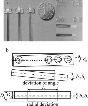
    Figure 2.  Research object a—fiber array and jamper b—assembly deviation diagram

    光纤阵列及连接头的对准偏差如图 2b所示。图中δα, δβ, δγ为光纤阵列与连接头的姿态偏差,δxδz为光纤阵列及连接头的径向偏差,D1D2分别为连接头与光纤阵列的直径,L为连接头的插槽长度。通过对光纤阵列及连接头的具体结构尺寸以及在空间中的对接关系分析,理论上需两零件对准的径向、姿态偏差分别小于(D1-D2)/2=(56-48.5)/2=3.75μm, arctan[(D1-D2)/L]=arctan[(56-48.5)/1400]=0.307°,因此, 通过分析光纤阵列与连接头间的对准偏差以验证组合系统的测量精度。

    搭建实验测试平台如图 3所示。该系统主要由成像单元、倾角仪辅助测量单元、位姿调整单元以及零部件夹持单元四部分组成。组合系统中远心镜头Ⅰ和Ⅱ的工作距离均为110mm,放大倍数分别为0.17, 0.3倍,景深分别为4.44mm, 11.2mm;CMOS图像传感器的分辨率与像元尺寸分别为1280×1024, 4.8μm×4.8μm;倾角仪测量范围与精度分别为±5°, 0.001°;调整机构包含转动滑台与电动平移台,调整范围分别为±5°, 20mm,调整分辨率分别为0.01°, 0.1μm。

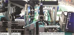
    Figure 3.  Experimental platform

    在对准过程中,组合测量系统基于倾角仪测量值结合上方夹具之间的位姿关系可求解出两夹具间的αm, t, βm, t对夹具Ⅱ进行调整修正,并保证特征点位于视觉成像系统的视野中。随后对特征点进行成像,并结合图像处理求解出两夹具间的水平方位角γm, t以及位置信息Tm, t, xTm, t, z, Tm, t, y,调整机构根据视觉求解信息依次对夹具Ⅱ进行调整,从而间接完成光纤阵列的位姿调整与对准任务。重复上述步骤,可获得多组实验结果, 如图 4所示。图中,光纤阵列与连接头的对准姿态偏差δα, δβδγ均小于0.307°,对准径向偏差δxδz均小于3.75μm。实验结果表明,组合测量系统可以有效地保证光纤阵列及连接头的空间位姿测量精度,进而保证了两零件的对准精度。

    为了验证组合测量系统的精度,采用3-D轮廓测量仪对装夹在夹具上的光纤阵列及连接头进行测量,通过获得光纤阵列及连接头的点云数据计算出两零件的空间相对位置(Tc, x, Tc, y, Tc, z)与姿态(αc, βc, γc);在保持相对位姿不变的情况下,再采用本文中构建的组合测量系统进行测量,获得光纤阵列与连接头的空间相对位置(Tm, t, x, Tm, t, y, Tm, t, z)与姿态(α, β, γ),进行多次测量获得对比实验数据,如表 1所示。

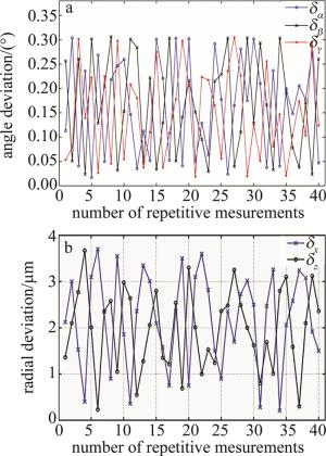
    Figure 4.  Alignment deviation curve

    relative position
    combined measurement 3-D profile measuring instrument position error
    (Tm, t, x, Tm, t, y, Tm, t, z)/mm (Tc, x, Tc, y, Tc, z)/mm Tx, ΔTy, ΔTz)/mm
    (-3.603, 0.604, 0.912) (-3.601, 0.603, 0.909) (-0.002, 0.001, 0.003)
    (2.729, 1.579, -0.124) (2.728, 1.577, -0.122) (0.001, 0.002, -0.002)
    (1.971, 0.013, -0.305) (1.969, 0.011, -0.302) (0.002, 0.002, -0.003)
    (1.384, 1.004, -0.524) (1.382, 1.003, -0.522) (0.002, 0.001, -0.002)
    (-1.064, 0.142, 0.917) (-1.062, 0.141, 0.915) (-0.002, 0.001, 0.002)
    (-0.753, 0.978, 1.392) (-0.752, 0.976, 1.389) (-0.001, 0.002, 0.003)
    relative attitude
    combined measurement 3-D profile measuring instrument attitude error
    (α, β, γ)/(°) (αc, βc, γc)/(°) α, Δβ, Δγ)/(°)
    (-1.068, 1.978, 1.837) (-1.063, 1.976, 1.833) (-0.005, 0.002, 0.004)
    (0.175, 2.168, -0.841) (0.172, 2.166, -0.839) (0.003, 0.002, -0.002)
    (0.976, -2.217, 0.735) (0.974, -2.223, 0.732) (0.002, -0.004, 0.003)
    (0.909, -1.528, -2.180) (0.908, -1.524, -2.183) (0.001, -0.004, -0.003)
    (-0.586, -0.335, -0.903) (-0.583, -0.331, -0.898) (-0.003, -0.004, - 0.005)
    (-0.886, 2.870, 2.081) (-0.882, 2.869, 2.078) (-0.004, 0.001, 0.003)

    Table 1.  Accuracy comparison of two measurement systems

    由于验证测试实验中选用的3-D轮廓测量仪的空间坐标点测量精度为(0.5μm, 0.5μm, 0.4μm),通过光纤阵列及连接头结构的点云数据计算出两者的相对空间位姿,其精度远高于光纤阵列对准所要求的适配精度。因此,将3-D轮廓测量仪测得的相对空间位姿作为组合测量系统的参考依据。经过数次测量对比实验表明:光纤阵列与连接头在空间位置为(±3mm, ±2mm, ±2mm)、姿态为(±3°, ±2°, ±3)的范围内,组合测量系统相对于3-D轮廓测量仪的测量结果其位置与姿态的偏差分别小于(±2μm, ±2μm, ±3μm), (±0.005°, ±0.004°, ±0.005°),验证了本文中构建的组合测量系统能够很好地满足光纤阵列与连接头在自动瞄准过程中的空间相对位姿的测量要求。

3.   结论
  • 针对微小型零件在宏-微跨尺度的空间位姿精密测量及自动化装配问题,本文中提出了一种基于正交双目视觉与倾角仪组合的空间位姿测量方法。结合测量系统中各模块的坐标转换关系,构建了空间位姿测量模型,并对其测量原理、空间位姿高精测量解析算法进行了详细的阐述与推导。为了验证组合测量系统的精度与可靠性,以光纤阵列及连接头为研究对象,搭建实验测试平台,进行重复性验证实验并对装配系统的对准偏差进行分析。同时,为了确保组合测量系统的精度,利用3-D轮廓测量仪进行精度验证。实验结果表明,组合测量系统测得的位置与姿态偏差分别小于(±2μm, ±2μm, ±3μm), (±0.005°, ±0.004°, ±0.005°),满足微小型零件空间位姿精密测量的要求,同时也为跨尺度微小型零件的位姿测量提供了新的参考方法。

Reference (16)

Catalog

    /

    DownLoad:  Full-Size Img  PowerPoint
    Return
    Return