 Map
Map


HTML
-
TC4钛合金薄壁件的加工难点主要体现在切削加工性差、材料去除率高和切削加工易变形等方面,从而导致加工效率低和加工成本高[1]。激光选区熔化(selective laser melting, SLM)是一种使用高能量激光束分层制造、逐层堆积的增材制造技术,能够制造出传统工艺不能生产的复杂薄壁件,且后续加工量少,被广泛应用在航天航空领域[2-3]。但SLM成形过程中易产生较大的残余应力,导致零件开裂、翘曲变形等成形缺陷[4],其中激光功率、扫描速率是激光能量密度输入的主要因素,SLM成形薄壁件厚度和扫描路径也有待确定。
在SLM成形薄壁件的研究中,研究人员通过研究SLM成形316L不锈钢薄壁件与工艺参量之间的关系,得出较优的工艺参量,并成形了变截面薄壁件[5-6]。LI等人[7]研究了SLM成形TC4钛合金薄壁件的偏差与扫描长度的关系, 得出最合适的扫描长度是在4mm~6mm之间。SONG等人[8]提出了一种新的分离零件模型法,以提高W-Cu合金薄壁件生产质量。在SLM成形件变形的研究中,LI等人[9]通过扩大热源尺寸和层厚,预测了SLM成形AlSi10Mg零件的变形,得出长度方向的残余应力是零件变形的主要因素。ZHANG等人[10]通过监测熔池的变化状态,判断SLM成形TC4钛合金过程中变形的产生,并表明试件的翘曲变形产生于成形初期。MAZUR等人[11]对SLM成形TC4钛合金晶格的变形和破坏行为进行了理论上的预测和实验验证,得出以伸展为主的变形机制。ZHANG等人[12]通过优化SLM成形合金支撑结构,发现采用分块0°倾斜支撑可以有效地减小零件的翘曲变形。在SLM成形件的残余应力研究中,一些学者采用热-力耦合模型,研究不同扫描策略对SLM成形的残余应力与变形影响规律,得到降低扫描线长度和交替扫描策略时残余应力较小[13-14]。也有学者通过对SLM成形316L不锈钢多道多层的残余应力研究,得出最大残余应力在基板结合处且随层高增加而增加,残余应力在扫描方向上高于垂直方向[15-16]。VRANCKEN等人[17]采用2维应力映射轮廓法对SLM成形产生的残余应力状态进行了研究,得出残余应力对SLM的各向异性行为有重大影响。然而,关于TC4钛合金薄壁件的变形与残余应力的研究却鲜有报道。
目前,为减小SLM成形件残余应力的措施主要有以下两种:一是从扫描策略或热处理等工艺参量考虑;二是对基板进行加热。DENG等人[18]通过研究不同扫描策略成形316L不锈钢零件,得出分区扫描策略可以减小残余应力。LIANG等人[19]研究发现SLM成形TC4钛合金的残余应力主要分布在生长方向,可以通过热处理来减小残余应力的累积。参考文献[20]中将基板加热到160℃,发现可以降低40%的残余应力。LIU等人采用数值模拟,获得激光冲击强化不同深度的残余应力场分布。
综上所述,作者采用SLM成形TC4钛合金薄壁件,考虑激光功率、扫描速率、薄壁厚度和扫描路径方向对试件变形与残余应力的影响,分析成形工艺参量与变形和残余应力之间的内在关系,测量不同深度的残余应力状态。得到高质量的钛合金薄壁件SLM成形工艺控制策略,为合理确定3-D打印件的精密切削加工余量奠定基础。
-
实验设备使用德国的Concept Laser M2激光成形机,激光波长为1064nm~1100nm,保护气体为体积分数为0.9999的氩气。成形材料使用无锡飞尔康公司生产的TC4钛合金粉末,其平均粒径为45μm,基板为TC4钛合金[22]。
-
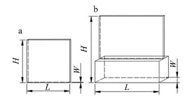
设计了两组试验方案:第1组方案中的激光功率分别为160W, 180W和200W,扫描速率分别为800mm/s, 1000mm/s和1200mm/s,具体参量见表 1。第2组方案中壁厚分别为0.2mm, 0.4mm, 0.6mm和0.8mm,扫描路径方向分别为0°, 45°和60°,具体参量见表 2。并设计了30mm×10mm×5mm的基座承接TC4钛合金薄壁件,扫描路径方向如图 1所示,即激光扫描策略也是蛇形扫描。各组试件成形示意见图 2。
specimen number wall thickness+height+length/mm forming process laser power P/W scanning speedv/(mm·s-1) powder layer thickness/μm scanning interval/μm scanningstrategy 1 0.6×20×20 160 800 30 105 snake scanning 2 0.6×20×20 160 1000 30 105 snake scanning 3 0.6×20×20 160 1200 30 105 snake scanning 4 0.6×20×20 180 1000 30 105 snake scanning 5 0.6×20×20 180 1200 30 105 snake scanning 6 0.6×20×20 180 800 30 105 snake scanning 7 0.6×20×20 200 1200 30 105 snake scanning 8 0.6×20×20 200 800 30 105 snake scanning 9 0.6×20×20 200 1000 30 105 snake scanning Table 1. SLM forming scheme with different laser power and scanning speeds
specimen number wall thickness+height+length/mm forming process laser power P/W scanning speedv/(mm·s-1) powder layer thickness/μm scanning interval/μm scanningstrategy 1 0.2×30×30 180 1200 30 105 0° 2 0.4×30×30 180 1200 30 105 0° 3 0.6×30×30 180 1200 30 105 0° 4 0.6×30×30 180 1200 30 105 45° 5 0.6×30×30 180 1200 30 105 60° 6 0.8×30×30 180 1200 30 105 0° 7 0.8×30×30 180 1200 30 105 45° 8 0.8×30×30 180 1200 30 105 60° Table 2. SLM forming scheme with different wall thicknesses and scanning path directions
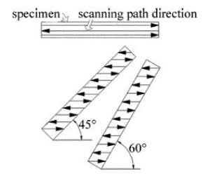
Figure 1. Direction diagram of scanning path

Figure 2. Forming schematic diagram of each specimen
-
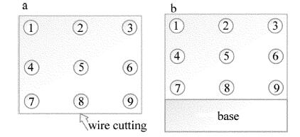
试件成形后,采用三坐标测量仪随机测量试件上的18个点,以其平面度作为变形。为了测量距离试样表面不同深度的残余应力,采用X射线应力测定仪(X-350A型)首先测定了试样未处理表面的残余应力,然后依次采用400目、600目、800目和1200目砂纸对试样表面进行粗磨并测量其表面残余应力,最后通过电解抛光(电解溶液是高氯酸和无水醋酸体积比1:4)得到30μm和80μm深度的表面并测量其表面残余应力。试件上X射线应力测量点如图 3所示。

Figure 3. Residual stress measurement point of specimens
1.1. 试验设备与材料
1.2. 试验方案
1.3. 变形和残余应力测量
-
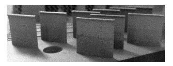
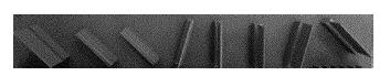
试验得到SLM成形TC4钛合金薄壁件的试样如图 4和图 5所示。

Figure 4. Sample plots of different laser power and scanning speeds

Figure 5. specimen drawing with different wall thicknesses and scanning path directions
-
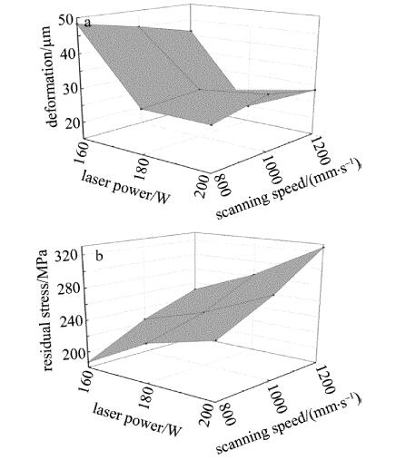
试件成形后,测得不同激光功率与扫描速率下的变形和各试样5号点的残余应力如图 6所示。由图 6a可得,SLM成形TC4钛合金薄壁件变形随着激光功率增大先减小后增大。当激光功率160W,变形随着扫描速率增加而减小;当激光功率为180W,变形随着扫描速率增加先增大后减小;当激光功率为200W,变形随着扫描速率增加先增大后减小,激光功率和扫描速率对试件变形存在交互作用。当激光功率为180W、扫描速率为1200mm/s时,试件变形最小为19.82μm。由图 6b可得,薄壁件的残余应力随着激光功率和扫描速率的增大而增大。当激光功率为160W、扫描速率为800mm/s时,试件5号点的残余应力最小为186.9MPa。

Figure 6. Effect of laser power and scanning speed on deformation and residual stress
分析认为,当激光功率较小时,熔池较小,导致TC4钛合金粉末熔化不充分,冷却时材料收缩与膨胀不协调,变形增大;此时残余应力较小是因为粘粉现象比较严重,测得的残余应力是表面粘粉状态下的。当激光功率较大时,熔池较大,粉末熔化充分,产生的温度梯度大,导致变形与残余应力都增大。
-
对不同薄壁厚度与扫描路径方向相同的试件测得变形与残余应力如图 7所示。由图 7a可得,TC4钛合金薄壁件的变形随壁厚增加先减小后增大,当壁厚为0.4mm、扫描路径方向为0°时,变形最小为16.71μm。对比线切割前后,发现线切割会增加试件变形,且与线切割前的影响趋势较为一致。由图 7b可得,选取试件中间点和右下点测得试件的残余应力随着壁厚增加先减小后增大,在壁厚为0.6mm时,试件残余应力最小,但试件的右下点数值上要大于中间点。
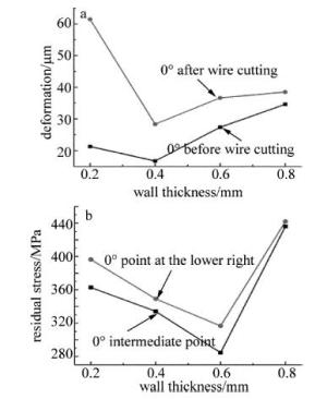
Figure 7. Effect of thin-walled thickness on deformation and residual stress
分析认为,成形较小壁厚试件时,考虑其熔池大小,单道扫描达不到壁厚要求,双道又超过壁厚,所以重熔区域较大,造成温度梯度大,导致变形与残余应力较大。线切割前后变形差异是由于线切割造成应力重新分布,产生新塑性应变,致使变形增大。但各试样线切割时长与切割区域都一样,都只是产生一定的塑性变形,故各试样线切割后的变形变化规律基本与初始一致。
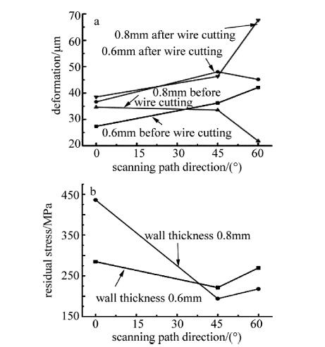
对壁厚0.6mm和0.8mm的试件扫描路径方向不同得到的变形和残余应力如图 8所示。由图 8a可得,当壁厚0.6mm时,变形随着扫描路径方向增加而增大。当壁厚为0.8mm时,变形随着扫描路径方向增加而减小。但在扫描路径方向为60°时,线切割前后变形趋势不一致。由图 8b可得,相同壁厚条件下,残余应力随扫描路径方向的增加而先增大后减小,即扫描路径方向为45°时,残余应力最小。相对来说,扫描路径方向对壁厚0.8mm的试件影响更为显著。

Figure 8. Effect of scanning path direction on deformation and residual stress
分析认为,扫描路径方向的不同,会导致重熔区域大小和时间不一样,从而造成温度梯度的差异,当扫描路径方向为45°时,各熔道间熔化较充分,温度梯度最小,产生的残余应力较小。
-
第1组5号试件和第2组3号试件的成形工艺参量一样,对其进行X射线应力测定,依次测得未处理表面、表面粗磨、电解30、电解80μm后的9个点残余应力值如图 9所示。
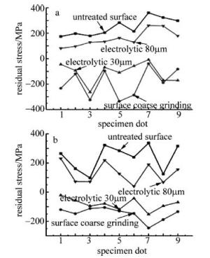
Figure 9. Residual stress measurement of specimens
由图 9a可得,未经处理的表面残余应力在170MPa~370MPa之间,且最大应力出现在7号点(试件底层左端)。从整体分析,残余应力有从成形件底层向顶层减少的趋势,在试件与基板界面结合的线切割处残余应力值偏大,左端残余应力大于右端。经表面粗磨处理后,残余应力变为压应力,其值在-40MPa~-340MPa之间。表面电解30μm后,对粗磨产生的表面残余应力影响不大。电解80μm后与未处理表面的残余应力分布较为一致,但在数值上更小。
分析认为,激光从左往右扫描,刚开始与基板融合时,产生的温度梯度大,造成较大残余应力。当下一层扫描到该点时,由于有一定的热积累效应,温度梯度变化较小,故表现为向顶层减小的趋势。砂纸粗磨会产生较大的压应力,改变其残余应力分布,测得的值应为压应力值。经电解抛光,逐层剥去试件表层材料,显示出内层的残余应力,但粗磨会产生一定的压应力层,初步电解剥落的材料有限,故表面电解30μm后还是处于压应力状态。表面的残余应力大于内层的是由于表面层与粉末直接接触,温度梯度大于内层。
由图 9b可得,未经处理的表面残余应力在90MPa~340MPa之间,且最大应力在底层7号点。同样,经表面粗磨后,残余应力变为负值,其值在-100MPa~-250MPa之间。对比图 9a,说明添加基座时,由于基座上有热积累效应,当开始打印薄壁件时,产生的温度梯度较小,残余应力也相应减小。
2.1. 不同激光功率与扫描速率的影响
2.2. 不同壁厚与扫描路径方向的影响

2.3. 相同工艺参量下残余应力分析

-
研究了激光功率、扫描速率、薄壁厚度和扫描路径方向对SLM成形TC4钛合金薄壁件变形与残余应力的影响,分析了不同工艺参量下的变形与残余应力差异。
(1) SLM成形TC4钛合金薄壁件变形随激光功率的增大先减小后增大,表面残余应力随激光功率和扫描速度增大而增大。相同工艺参量下,薄壁件的变形与残余应力随壁厚先减小后增大,相同壁厚条件下,成形最佳扫描路径方向是45°。
(2) TC4钛合金薄壁件变形主要在顶层两侧边角,最大残余应力主要分布在试件底层,以及薄壁件中间,且有从基板向顶层减少的趋势。当激光功率为180W、扫描速率为1200mm/s时,试件变形最小;当壁厚为0.6mm,扫描路径方向为45°时,试件残余应力最小。
(3) 通过在TC4钛合金薄壁件上添加基座能有效的减少线切割后的变形与残余应力。通过砂纸粗磨和电解抛光,表明砂纸粗磨后产生压应力,初步表面电解30μm后还是处于压应力状态,未处理的表面残余应力大于内层表面残余应力。
 DownLoad: