Advanced Search

ISSN1001-3806 CN51-1125/TN Map

Volume 43 Issue 3
Mar.  2019
Article Contents
Turn off MathJax

Citation:

Structure optimization and test verification of two-circle coaxial optical fiber sensors

  • Corresponding author: YANG Ruifeng, yangruifeng@nuc.edu.cn
  • Received Date: 2018-07-11
    Accepted Date: 2018-08-15
  • In order to verify the feasibility of the mathematical model of two-circle coaxial optical fiber sensors for measuring the surface topography of objects, the parameters of the novel structure optical fiber sensor were optimized to improve the linear measurement range and sensitivity of the optical fiber sensors. The mirror paper, which does not affect the front slope data of the modulation characteristic curve, was used as the reflector for experimental verification. The theoretical analysis and mathematical modeling of the new structure of optical fiber sensor were also carried out. Then, the tilt angle of the novel structure was optimized by using particle swarm optimization. The results show that the experimental curve obtained by using mirror paper as reflector coincides with the simulation modulation characteristic curve. The feasibility of the mathematical model of the two-circle coaxial optical fiber sensor used to measure the surface topography of the object is proved. The slope angle optimized by particle swarm optimization is 2.33°. At this time, the linear measurement range and sensitivity of the front slope are 1.14 times and 1.89 times respectively when the inclination angle is zero. The novel structure of two-circle coaxial optical fiber sensor shows good measurement performance and application prospects.
  • 加载中
  • [1]

    HUI M. Algorithm and experimental study of phase-shift interferometry in surface microtopography measurement[D]. Xi'an: Xi'an Institute of Optics and Precision Mechanics, Chinese Academy of Sciences, 2001: 11-12(in Chinese).
    [2]

    CAI C L, WANG Y, FENG J L, et al. Optical fiber sensor for the coal mine dust mass concentration in well testing[J]. Optical Instruments, 2017, 39(2):8-11(in Chinese).
    [3]

    ZHU Sh Y, CAO H M. Theoretical modeling and simulation implementation of reflective optical fiber bundle probe[J]. Instrument Technique and Sensor, 2013, 50(5):75-78(in Chinese).
    [4]

    CAO Y L, HAN J G, XIONG X M. Study on application of optical fiber displacement sensor in measurment of PET bottle wall thickness[J]. Laser Technology, 2018, 42(6):817-821(in Chinese).
    [5]

    ZHAO Y, LIU L H. Fiber-optical sensor system used for complex surface digitizing[J]. Chinese Journal of Scientific Instrument, 2002, 23(5):540-543(in Chinese).
    [6]

    LI L J. Research on application of target laser scattering characteristics in microscopic surface profile precision measurement of steel plates[D]. Changchun: Changchun University of Science and Technology, 2005: 4-5(in Chinese).
    [7]

    XU T, LV H B, YANG H Y, et al. Research of a reflective fiber-optic displacement sensor with intensity compensation[J]. National University of Defense Technology, 2000, 45(6):109-112(in Chinese).
    [8]

    WANNINAYAKE I B, DASGUPTA P, SENVIRATNE L D, et al. Modeling and optimizing output characteristics of intensity modulated optical fiber-based displacement sensors[J]. IEEE Transactions on Instrumentation & Measurement, 2015, 64(3):758-767.
    [9]

    YANG X H. The research on reflective intensity-modulated fiber-optical displacement sensor and applications in digital gauge[D]. Chengdu: Sichuan University, 2004: 19-23(in Chinese).
    [10]

    ZHONG Zh, PENG H, SHAN M G, et al. Modeling intensity-mo-dulated characteristics of inclined-fiber receiving distance sensor with single mode illumination[J]. Proceedings of the SPIE, 2010, 7749:774917. doi: 10.1117/12.869395
    [11]

    HUANG H, TATA U. Simulation, implementation, and analysis of an optical fiber bundle distance sensor with single mode illumination[J]. Applied Optics, 2008, 47(9): 1302-1309. doi: 10.1364/AO.47.001302
    [12]

    PUANGMALI P, ALTHOEFER K, SENEVIRATNE L D. Mathematical modeling of intensity-modulated bent-tip optical fiber displacement sensors[J]. IEEE Transactions on Instrumentation & Measurement, 2010, 59(2):283-291.
    [13]

    LANG G W, YANG R F, GUO Ch X, et al. Design of concave ladder reflection optical fiber sensing prob[J]. Instrument Technique and Sensor, 2018, 55(2):4-6(in Chinese).
    [14]

    ZHU R X. Research of reflective intensity modulated fiber optic micro-displacement and angular displacement sensor[D]. Beijing: China University of Geosciences, 2017: 25-31(in Chinese).
    [15]

    PAN T T. Design and application of static ice pressure detection system based on RIM-FOPS[D]. Taiyuan : Taiyuan University of Technology, 2015: 22-31(in Chinese).
    [16]

    ZHAO Y. Fiber-optic complex contour surface detection and three-dimensional reconstruction technology[D]. Harbin: Harbin Institute of Technology, 2001: 27-28(in Chinese).
    [17]

    WANG X M, WANG H F, YAO N F. Parameter optimization of laser displacement sensor based on particle swarm optimization algorithm[J]. Laser Technology, 2018, 42(2):181-186(in Chinese).
    [18]

    BOERINGER D W, WERNER D H. Particle swarm optimization versus genetic algorithms for phased array synthesis[J]. IEEE Transactions on Antennas & Propagation, 2004, 52(3):771-779.
    [19]

    LUO H. A inertia weight adaptive particle swarm optimization algorithm[J]. Electronic Science and Technology, 2017, 30(3):30-32(in Chinese).
    [20]

    GAN C, CAO W, WU M, et al. A new bat algorithm based on ite-rative local search and stochastic inertia weight[J]. Expert Systems with Applications, 2018, 104(8):202-212.
  • 加载中
通讯作者: 陈斌, bchen63@163.com
  • 1. 

    沈阳化工大学材料科学与工程学院 沈阳 110142

  1. 本站搜索
  2. 百度学术搜索
  3. 万方数据库搜索
  4. CNKI搜索

Figures(8) / Tables(1)

Article views(6954) PDF downloads(17) Cited by()

Proportional views

Structure optimization and test verification of two-circle coaxial optical fiber sensors

    Corresponding author: YANG Ruifeng, yangruifeng@nuc.edu.cn
  • School of Instrument and Electronics, North University of China, Taiyuan 030051, China

Abstract: In order to verify the feasibility of the mathematical model of two-circle coaxial optical fiber sensors for measuring the surface topography of objects, the parameters of the novel structure optical fiber sensor were optimized to improve the linear measurement range and sensitivity of the optical fiber sensors. The mirror paper, which does not affect the front slope data of the modulation characteristic curve, was used as the reflector for experimental verification. The theoretical analysis and mathematical modeling of the new structure of optical fiber sensor were also carried out. Then, the tilt angle of the novel structure was optimized by using particle swarm optimization. The results show that the experimental curve obtained by using mirror paper as reflector coincides with the simulation modulation characteristic curve. The feasibility of the mathematical model of the two-circle coaxial optical fiber sensor used to measure the surface topography of the object is proved. The slope angle optimized by particle swarm optimization is 2.33°. At this time, the linear measurement range and sensitivity of the front slope are 1.14 times and 1.89 times respectively when the inclination angle is zero. The novel structure of two-circle coaxial optical fiber sensor shows good measurement performance and application prospects.

引言
  • 表面形貌的测量对精密机械制造、电子工业以及生物医学等领域的研究发挥着很重要作用[1]。光学测量技术因具有测量精度高、非接触、成本低等优点被应用于表面形貌的测量。其中以光纤作为传感单元的反射式强度调制型光纤传感器因结构简单、分辨率较高、设计灵活、性能可靠等优点得到了极大的关注[2-4]

    利用反射式强度调制型光纤传感器测量表面形貌的方法是先测得位移, 然后利用离散点的位移数据进行3维重构,进而还原表面形貌[5], 因此光纤传感器测量表面形貌的关键是测得准确的位移。双圈同轴式光纤传感器结合比值法可用于因被测表面经切削、研磨等加工过程中由于温度和压力等因素的变化,导致表面各处反射率不同的形貌测量[6-7]。为提高测量性能,国内外很多学者对光纤位移传感器进行了结构设计、数学建模和仿真计算[8-10]。HUANG等人提出了发送光纤与接收光纤有错位量可以减小传感器测量死区的大小[11]。PUANGMALI等人提出了弯曲尖端探头可以提高光纤位移传感器的测量范围[12],但都未针对固定结构的光纤探头进行定量分析。LANG等人提出了一种内凹阶梯形的探头结构来提高光纤位移传感器的灵敏度,但其仿真所用的均匀光强分布和实际高斯光强分布有较大偏差[13]。除此之外,以上研究在进行仿真实验时大都没有按照标准单模、多模光纤的数据进行仿真, 也未对固定结构的光纤传感器测量模型进行试验验证[14-15]

    为证明使用双圈同轴型光纤传感器测量表面形貌模型的可行性,作者进行了试验验证,并基于原始双圈同轴型光纤传感器结构, 引入外圈接收光纤倾斜角以同时改善双圈同轴型光纤传感器的测量范围和灵敏度,从而提高测量范围和速度。

1.   双圈同轴型光纤传感器的数学模型和试验验证
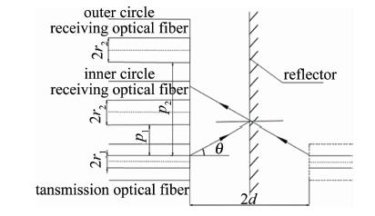
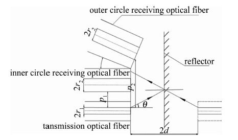
  • 双圈同轴型光纤传感器可利用外圈接收功率与内圈接收功率做比值, 以消除由部分表面密度和材质的不同导致反射率不同带来的干扰,还可以减小因光源强度的变化以及光纤的损耗等对测量造成的影响。双圈同轴型光纤传感器的结构简图如图 1所示。发送光纤为轴心,两圈接收光纤以同心圆的结构紧密排列在发送光纤周围。发送光纤采用芯径r1=4.5μm、数值孔径dNA=0.12的单模光纤,接收光纤采芯径r2=32.5μm的多模光纤, 发送光纤和接收光纤的包层直径均为125μm,激光器波长为1550nm。在此波段下单模光纤的归一化频率为2.272(小于2.405),所以经单模光纤的出射光强分布为高斯分布[16]。光强沿径向呈高斯分布理论模型为:

    Figure 1.  Structure diagram of two-circle coaxial optical fiber sensor

    结合Beckman散射理论、反射光强模型和透射等效法可以得到经反射面反射后的光强调制函数及单根接收光纤接收到的光功率, 如下式所示:

    式中,s为与发送光纤中心的径向距离,2d表示出射光纤端面到镜像反射面的距离,w2d为出射光在距离2d处的模场半径,P0为激光器的功率,P为接收光纤接收到的光功率,p为发送光纤和接收光纤纤芯之间的距离,C为菲涅耳界面反射系数,在玻璃和空气交界面时取0.04。单根内圈接收光纤和外圈接收光纤接收到的光强因p的不同而不同。

    为验证该种数学模型,采用平面镜作为被测面, 以图 2所示的测量系统进行测量。试验时发现,用厚度为1.84mm的平面镜测量时,内圈功率曲线前坡部分丢失。结合仿真结果来看,导致前坡丢失的原因是平面镜的真正反射面是其涂层,涂层前的玻璃厚度超过了部分前坡测量区间。因此,试验中创新性地使用厚度0.02mm的镜子纸作为被测面,以保证被测面最接近数学模型中的反射面表面形貌特征,同时保留调制特性曲线的前坡数据。经去除坏点程序后,测量部分数据如表 1所示。P1P2分别表示内圈接收光纤接和外圈接受光纤接收到的光功率。

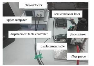
    Figure 2.  Platform for measuring the surface microstructure of an object

    displacement d/μm 0 1000 2000 3000 4000 5000
    inner circle power P1/mW 0 0.4135 0.1973 0.1117 0.0750 0.0521
    outer circle power P2/mW 0 0.2270 0.1584 0.1016 0.0704 0.0527
    ratio P2/P1 0 0.5490 0.8028 0.9096 0.9387 1.0115

    Table 1.  Optical power and ratio received by the inner circle and outer circle receiving fiber

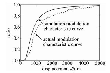
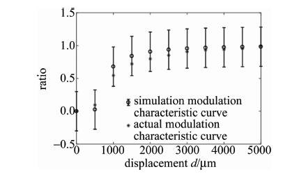
    图 3中是经过归一化后的试验比值调制特性曲线和仿真比值调制特性曲线对比图。图 4表明, 试验曲线在仿真曲线的标准差误差范围内(仿真曲线数据的标准差为0.342),两条曲线是吻合的。因此可以说明(2)式中用于测量反射率分布不均匀的物体表面形貌的光强模型是可行的。

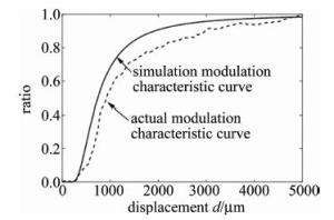
    Figure 3.  Comparison of characteristic curve between the simulated modulation and the experimental modulation

    Figure 4.  Error bar graph of simulation curve and test curve

2.   新结构双圈同轴型光纤传感器的建模与优化
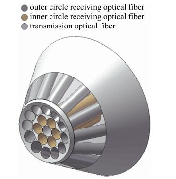
  • 为有效扩大双圈同轴式光纤传感器的测量范围和灵敏度,引入了外圈接收光纤的倾斜角β。外圈接收光纤以相邻的内圈接收光纤为轴沿顺时针旋转β图 5图 6分别为含倾斜角β同轴时光纤探头的结构简图和轴测图。引入倾斜角还可以改善因表面某些曲率变化较大的点测不准的情况。

    Figure 5.  Structure diagram of fiber optical sensor with outer circle fiber inclinable

    Figure 6.  Axial map of fiber optical sensor with outer circle fiber inclinable

    外圈接收光纤倾斜了角度β后接收到的光功率发生了变化。(2)式中的光纤间距p变为p′=r1cosβ-2dsinβ+pwcosβ+r2,其中,pw为外圈接收光纤距离发送光纤的距离。模场半径也随着p的变化而变化,${w_{2d}}^\prime = \left( {{p^\prime }\sin \beta + 2d\cos \beta } \right)\tan (\theta - \beta ) + {r_1}\cos \beta $,其中,θ为单模光纤的最大出射角度, θ=arcsindNA=arcsin0.12=6.89°。

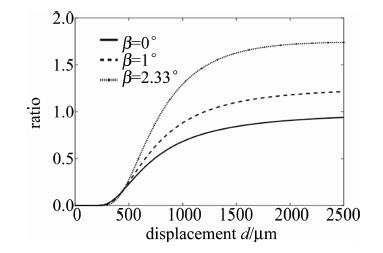
    利用MATLAB分别对当对倾斜角β=0°和β=1°进行仿真计算,仿真结果如图 7所示。可以看出, 比值调制特性曲线的线性测量区间、灵敏度和死区都发生了变化,线性测量范围和灵敏度都明显增大了。随着倾斜角度的增大,测量范围和灵敏度都会不断增大,但增加到一个最大值之后会因为倾斜角度过大外圈接收光纤接收不到光,因此,可采用粒子群算法寻求最大值来对倾斜角度进行优化,以获得能使接收光纤接收到的光最多的倾斜角度[17]

    Figure 7.  Ratio modulation characteristic curve of different inclination angles

  • 粒子群算法模仿鸟类飞行准则,其信息共享机制是一种共生合作的行为,即每个粒子都在不停的进行搜索,在其搜索过程中受到群体其它个体和自身经验的影响,并对自己的飞行速度和位置进行不断更新,同时具有历史最佳位置的记忆[18],其速度和位置更新公式如下:

    式中,i表示第i个粒子,vi(t)和xi(t)分别表示第i个粒子进化到t代时的速度与位置,pi, best(t)表示粒子i进化到t代时的个体最优位置,gbest(t)表示进化到t代整个粒子群的最优位置。m1m2为0~1的随机数,c1=c2=1.496是加速因子[19]W为惯性权重,线性递减的动态惯性权重W=Wmax-(WmaxWmin)i/T可以平衡全局搜索和局部搜索能力[20],其中Wmax=0.8,Wmin=0.4。

    将倾斜角β和位移d作为粒子群算法的输入,来寻求比值的最大值位置。(2)式中的光强调制函数作为适应度函数。倾斜角β取0°~6°,因为倾斜角不能超过单模光纤的最大出射角。位移d的取值范围为0μm~2500μm。迭代次数T=200,并以迭代次数作为算法结束条件,优化结束后适应度函数如图 8所示。

    Figure 8.  Fitness evolution curve

    经粒子群算法运算可得:当β=2.33°且d=2500μm时,比值调制特性函数取最大值,最大值为1.744, 即当倾斜角取2.33°时,接收光纤所能接收的光达到了最大值,线性测量区间由β=0°时的[386μm 732μm]增大到了[452μm 845μm], 灵敏度表现为前坡线性测量区间的斜率,β=0°时的灵敏度为1.212×10⁻³β=2.33°时的灵敏度为2.287×10⁻³,较原来提高了约1.89倍。新结构的双圈同轴型光纤传感器的测量性能得到了提升。利用粒子群算法优化的过程中发现,当倾斜角度超过2.33°且测量距离d超过2500μm时,由于内圈接收光纤相比外圈接受光纤接收到的光小很多,使比值接近无穷大,应舍弃不用。

3.   结论
  • 根据双圈同轴型光纤传感器的结构和光强分布的特点,建立了测量物体表面形貌传感器的数学模型并利用镜子纸作为反射面进行了试验验证。经对比仿真结果和试验验证结果, 证明了所用数学模型是可行的。利用粒子群算法对新结构传感器中的倾斜角度进行了优化,优化结果表明,当倾斜角β=2.33°时, 这种新结构的光纤传感器的线性测量范围可扩大到400μm左右,灵敏度约为2.287×10⁻³,提高了测量表面形貌时的速度。该结构对此类光纤传感器的设计、研究以及实际应用提供了参考。试验中所采用的镜子纸比较接近理想表面,但实际中部分被测表面因由加工时产生不可避免的微小纹理所导致的反射率不同会给测量带来误差,要减小这种误差还需进一步的研究。

Reference (20)

Catalog

    /

    DownLoad:  Full-Size Img  PowerPoint
    Return
    Return