Advanced Search

ISSN1001-3806 CN51-1125/TN Map

Volume 43 Issue 2
Jan.  2019
Article Contents
Turn off MathJax

Citation:

Study on microstructure and properties of 5mm thick copper laser welded joints

  • Received Date: 2018-04-17
    Accepted Date: 2018-04-26
  • In order to study effect of defocus amount on the weld formation, the microstructure characteristics and properties of 5mm thick laser welding copper, metallographic microscope was used to analyze the microstructure and morphology of the weld.The tensile strength and electrical conductivity of the joint were tested.The results show that, when the absolute value of defocus is high, it is easy to spatter and cause holes on the weld surface.A well-formed weld can be obtained within the defocus range of 0mm~-2mm.The angle between the columnar crystal and the welding direction of the longitudinal section of the weld is gradually reduced from 90°on the sides to 0°in the middle.The columnar crystal near the upper surface of the weld is about 2.96 times the length of the columnar crystal near the bottom surface.The grain size of heat affected zone coarsen.And the width of heat affected zone corresponding to defocus+1mm is the largest.Under the penetration condition, the tensile strength of the joints corresponding to the different defocus amounts is equal, up to 77.3% of base metal.The joint elongation with defocus 0mm~-1mm is slightly higher than that with defocus-1mm~-4mm, up to 54.9% of base metal.The electrical conductivity of the weld is almost the same as that of the base metal.The study is beneficial to obtain good shaped laser welded joints of copper.
  • 加载中
  • [1]

    BIRO E, WECKMAN D C, ZHOU Y. Pulsed Nd:YAG laser welding of copper using oxygenated assist gases[J]. Metallurgical & Materials Transactions, 2002, A33(7):2019-2030.
    [2]

    HESS A, WEBER R, HEIDER A, et al. Forced deep-penetration welding with low-power second-harmonic assistance of CW copper welding with 1μm wavelength[J]. Physics Procedia, 2010, B5:29-36.
    [3]

    ZHANG L J, ZHANG G F, NING J, et al. Microstructure and pro-perties of the laser butt welded 1.5mm thick T2 copper joint achieved at high welding speed[J]. Materials & Design, 2015, 88:720-736.
    [4]

    HESS A, SCHUSTER R, HEIDER A, et al. Continuous wave laser welding of copper with combined beams at wavelengths of 1030nm and of 515nm[J]. Physics Procedia, 2011, A12:88-94.
    [5]

    HEIDER A, STRITT P, HESS A, et al. Process stabilization at welding copper by laser power modulation[J]. Physics Procedia, 2011, A12:81-87.
    [6]

    JIAO J K, WANG F Y, SUN J Q, et al. Study on copper surface pre-treating and welding with fiber lasers[J]. Laser & Optoelectronics Progress, 2016, 53(3):031409(in Chinese).
    [7]

    WU X H, XIANG F W, LIU Y, et al. Study on laser welding of co-pper[J]. Applied Laser, 2013, 33(2):169-172(in Chinese). doi: 10.3788/AL
    [8]

    HEIDER A, SOLLINGER J, ABT F, et al. High-speed X-ray analysis of spatter formation in laser welding of copper[J]. Physics Procedia, 2013, 41:112-118. doi: 10.1016/j.phpro.2013.03.058
    [9]

    QIN G L, LIN Sh Y. Radial dimension of keyhole and its dynamic characteristics in laser deep penetration welding[J].Chinese Journal of Lasers, 2005, 32(4):557-561(in Chinese).
    [10]

    ZUO T Ch. Laser materials processing of high strength aluminum alloys[M]. Beijing:National Defense Industry Press, 2002:74(in Chinese).
    [11]

    WANG J Ch, WANG X Zh, HUI S X. Research of linear heat input and laser focus position for laser welding HE130 titanium alloy[J].Chinese Journal of Lasers, 2003, 30(2):179-184(in Chinese).
    [12]

    QIANG H L, CHENG Zh G, LUO J T, et al. Influencing factors on topography of weld in deep penetration laser welding[J].Acta Optica Sinica, 1999, 19(9):1289-1295(in Chinese).
    [13]

    LU L, SHEN Y F, CHEN X H, et al. Ultrahigh strength and high electrical conductivity in copper[J]. Science, 2004, 304(5669):422-426. doi: 10.1126/science.1092905
    [14]

    CALLISTER W D, RETHWISCH D G. Materials science and engineeringan introduction[M]. NewYork, USA:Wiley, 2000:736.
    [15]

    XUE P, XIAO B L, ZHANG Q, et al. Achieving friction stir welded pure copper joints with nearly equal strength to the parent metal via additional rapid cooling[J]. Scripta Materialia, 2011, 64(11):1051-1054. doi: 10.1016/j.scriptamat.2011.02.019
  • 加载中
通讯作者: 陈斌, bchen63@163.com
  • 1. 

    沈阳化工大学材料科学与工程学院 沈阳 110142

  1. 本站搜索
  2. 百度学术搜索
  3. 万方数据库搜索
  4. CNKI搜索

Figures(10) / Tables(3)

Article views(7422) PDF downloads(88) Cited by()

Proportional views

Study on microstructure and properties of 5mm thick copper laser welded joints

  • 1. Guangdong Welding Institute(China-Ukraine E. O. Paton Institute of Welding), Guangzhou 510650, China
  • 2. Guangdong Provincial Key Laboratory of Advanced Welding Technology, Guangzhou 510650, China

Abstract: In order to study effect of defocus amount on the weld formation, the microstructure characteristics and properties of 5mm thick laser welding copper, metallographic microscope was used to analyze the microstructure and morphology of the weld.The tensile strength and electrical conductivity of the joint were tested.The results show that, when the absolute value of defocus is high, it is easy to spatter and cause holes on the weld surface.A well-formed weld can be obtained within the defocus range of 0mm~-2mm.The angle between the columnar crystal and the welding direction of the longitudinal section of the weld is gradually reduced from 90°on the sides to 0°in the middle.The columnar crystal near the upper surface of the weld is about 2.96 times the length of the columnar crystal near the bottom surface.The grain size of heat affected zone coarsen.And the width of heat affected zone corresponding to defocus+1mm is the largest.Under the penetration condition, the tensile strength of the joints corresponding to the different defocus amounts is equal, up to 77.3% of base metal.The joint elongation with defocus 0mm~-1mm is slightly higher than that with defocus-1mm~-4mm, up to 54.9% of base metal.The electrical conductivity of the weld is almost the same as that of the base metal.The study is beneficial to obtain good shaped laser welded joints of copper.

引言
  • 激光焊接具有高能量密度、焊缝深宽比大、热影响区(heat affected zone,HAZ)窄、焊件变形极小、非接触和无需真空等优势,但紫铜对激光具有低吸收率和高导热性,研究表明[1]:紫铜在室温下对1000nm波长激光的吸收率为4.98%,在紫铜熔点时的吸收率也仅为16.1%,所以紫铜激光焊接仍有很大挑战性。随着工业需求的不断增加,紫铜激光深熔焊受到国内外的极大关注。国内外学者对紫铜激光焊接的工艺[2-8]、组织特征[3]、力学性能[3]方面做了一些研究,但主要集中在紫铜薄板激光功率、焊接速率对焊缝成形影响的研究,涉及中厚板紫铜激光焊接工艺较少。影响紫铜激光焊接的焊缝成形质量和力学性能主要工艺因素包括激光功率、焊接速率、离焦量、倾斜角度,在其它工艺参量一定的情况下,离焦量的变化会导致工件表面激光能量密度与传输效率的差异,影响到焊缝熔宽、熔深、成形质量等,进而影响其力学性能。

    本文中采用碟片激光器对5mm厚紫铜进行对接实验,研究离焦量工艺参量对5mm厚紫铜激光焊接焊缝成形的影响, 并研究焊接接头组织特征和性能,以期为5mm厚紫铜激光焊接提供实验数据和理论基础,具有重要现实意义。

1.   实验材料及方法
  • 实验设备采用Trumpf Trudisk10002型碟片型激光器,额定最大输出功率为10kW,准直焦距为200mm,聚焦焦距为200mm,传输光纤为200μm。实验材料所采用紫铜的试样尺寸为110mm×100mm×5mm,其成分(质量分数)如表 1所示。实验前用钢刷清洁工件表面,再用丙酮、酒精、去离子水超声清洗表面去除油污以及杂质。

    elements Cu O Fe S Ni
    mass fraction >0.9990 <0.0006 <0.00005 <0.00005 <0.000008

    Table 1.  Chemical compositions (mass fraction) of the materials

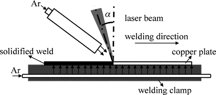
    图 1为紫铜激光焊接示意图。图中,α为光束的倾斜角度,由于紫铜对激光具有高反射率,所以光束必须有一定倾斜角。实验中α角度设置为12.5°,该角度为安全角度,使得反射能量不至于达到激光头。激光功率为9.5kW,焊接速率为2.1m/min,离焦量如表 2所示,并定义焦点在表面以上为正。

    Figure 1.  Experiment setup for laser welding of copper

    sample No. defocusing distance/mm
    1# +3
    2# +2
    3# +1
    4# 0
    5# -1
    6# -2
    7# -3
    8# -4

    Table 2.  Laser welding parameters

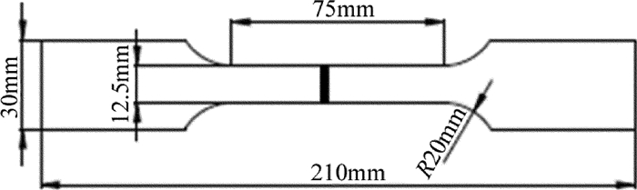
    采用金相显微镜对焊接接头观察微观组织及断裂亚表面,用50mL HCl+5g FeCl3+100mL H2O比例的腐蚀液进行金相腐蚀,用扫描电镜观察拉伸断裂断口。定义离焦量为F(mm),焊缝熔深为Hp(mm),焊缝正面宽度为Wu(mm),焊缝背面宽度为Wb(mm)。采用FD-102数字便携式涡流导电仪测试焊缝及母材的电导率。常温拉伸试样在CP-TS2000/100kW万能拉伸试验机进行,加载速率为1mm/min。拉伸试样形状尺寸根据GB/T228-2002设计,其尺寸示意如图 2所示。

    Figure 2.  Sketch of tensile sample size

2.   实验结果与分析
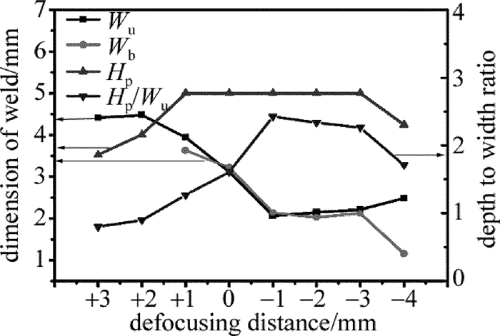
  • 图 3为不同离焦量对应的紫铜激光焊接焊缝外观。离焦量F=+3mm时,焊接过程有少量飞溅,焊缝正面有形成孔洞,凸起不均匀,焊缝未焊透;离焦量F=+2mm时,焊缝正面有孔洞,焊缝背面大部分为未熔透,有少量点透;离焦量在+1mm~-3mm范围内,焊缝焊透;离焦量F=+1mm时,焊缝严重下塌;离焦量在0mm~-2mm范围内,焊缝表面基本无飞溅,无明显孔洞,成形良好;离焦量在-3mm~-4mm范围内,焊缝正面有少量孔洞,反面凹凸不平。说明在高离焦量绝对值时,焊接过程不稳定,易出现飞溅造成焊缝表面孔洞,离焦量在0mm~-2mm范围内可获得成形良好的焊缝。图 4为离焦量对焊缝尺寸的影响。由图可知,熔深呈现先增后减规律,正面熔宽呈现先减规律后增规律,反面熔宽呈现减少规律,深宽比在离焦量F=+1mm~-4mm范围内大于1,说明在这个范围内,激光热量倾向于往深度方向扩散,焊缝以深熔焊形式存在。研究表明[9-12],金属材料在激光加热50μs~200μs时开始熔化,并出现部分气化,产生高压蒸气,并以极高的速度喷射出来;之后,高浓度气体(金属蒸气和辅助气体)使液相金属运动至熔池边缘,并在熔池中心形成小孔。当焦点位置为负时,材料内部的激光功率密度比工件表面还要高,因此能够形成更强的熔化和气化, 并使激光能量向材料的更深处传递,负离焦相比于正离焦可在更大工艺区间内获得深宽比大于1的焊缝,在离焦量F=+1mm时,由于焊缝宽度方向金属熔化量增加,熔池本身重力增加,进而引起焊缝下榻。

    Figure 3.  Appearance of laser welded copper joints with different defocus amounts

    Figure 4.  Relationship between dimension of weld and defocusing distance

  • 图 5为4#试样焊缝横截面的显微组织照片。由图可知,紫铜的母材为典型轧制态,显微组织为沿轧制方向拉长的细小晶粒,热影响区晶粒发生粗化,焊缝横截面左右两侧显微组织为水平方向的柱状晶,焊缝中间显微组织为平行于厚度方向的柱状晶。图 6为离焦量对焊缝热影响区宽度的影响。由图可知,离焦量F=+3mm~+2mm及F=-2mm~-4mm工艺参量下, 对应的焊缝热影响区宽度相当,离焦量F=+1mm工艺参量下对应的焊缝热影响区宽度最大,约为最小热影响区宽度的2.08倍。图 7为4#试样焊缝纵截面的显微组织照片。由图可知,焊缝纵截面左右两侧的显微组织为与焊接方向呈一定角度的柱状晶,焊缝柱状晶角度由两侧的90°逐步降低为中间的0°。这是由于焊缝不同区域热流方向不同,两侧到中间的热流方向变化规律:与焊接方向之间的角度由两侧的90°逐步降低为0°,导致柱状晶粒生长方向不断发生偏转。靠近焊缝上表面柱状长度约为1625.01μm,靠近焊缝下表面柱状长度约为549.72μm,前者约为后者的2.96倍,由此推测焊缝上表面冷却速度低于焊缝下表面。

    Figure 5.  Microstructure morphology of cross section of weld bead of sample 4#

    Figure 6.  Effectof defocusing distance on the width of HAZ

    Figure 7.  Microstructure morphology of longitudinal section of weld bead

  • 表 3为焊接接头的拉伸性能。由表 3可知, 焊接接头拉伸断裂于焊缝处,焊接接头的抗拉强度和延伸率较母材发生显著降低,焊透情况下的不同离焦量对应的焊接接头的拉伸强度相当,可达母材的77.3%,离焦量F=0mm~-1 mm对应的接头延伸率略高于离焦量F=-1mm~-4 mm对应的接头延伸率,可达母材的54.9%。图 8为紫铜拉伸断口形貌。母材和焊缝的断口形貌都显示韧窝断口特征,但焊缝的断口韧窝相对较小,说明其塑性较差。相比于轧制态母材的细小晶粒,焊缝晶粒为粗化的柱状晶,会对焊接接头的抗拉强度和延伸率都产生不利的影响,同时在高离焦量绝对值情况下,材料表面对激光吸收率下降,容易造成能量不足,熔池存在时间缩短,熔池中气泡难以逸出,引起焊缝内部气孔缺陷,如图 8f中箭头所示,导致焊接接头的延伸率进一步下降。图 9为4#试样焊缝拉伸断裂亚表面图。由图可知,焊缝上部塑性变形明显大于焊缝下部,断裂倾向沿着中间柱状晶处断裂,这是由于焊缝上部柱状晶长度较长,抵抗塑性变形能力较弱,在拉伸过程优先发生塑性变形,平行于力学方向的柱状晶抗拉强度优于垂直于拉伸方向中间柱状晶,所以断裂倾向沿着从中间柱状晶断裂。

    sample No. defocusing
    distance/mm
    tensile
    strength/MPa
    elongation/% fracture
    location
    base metal 295 19.1 base metal
    3# +1 192 10.5 weld
    4# 0 214 10.0 weld
    5# -1 218 7.0 weld
    6# -2 228 8.0 weld
    7# -3 215 7.0 weld
    8# -4 211 5.5 weld

    Table 3.  Tensile properties of welded joints

    Figure 8.  Fracture morphologies of copper

    Figure 9.  Sub+surface tensile fracture morphology of sample 4#

  • 相关研究指出晶界、位错、杂质原子的存在,都会对导电电子起了散射作用,会降低金属电导率[13]。通过加工硬化或者添加微量元素固溶处理来提高紫铜的抗拉强度方式往往会降低紫铜的电导率[14]。在焊接热循环过程中,热影响区和焊缝区域的位错数量会大幅度减少[15]。由图 10可知,焊缝电导率与母材几乎一样,可达母材电导率的98.6%,说明激光焊接焊缝晶粒的粗化并不会导致紫铜电导率发生明显变化,同时由于紫铜激光焊接是在氩气保护气氛进行,能避免焊缝氧化,减小对焊缝电导率影响。

    Figure 10.  Relationship between electrical conductivity and distance from weld center line

3.   结论
  • (1) 在高离焦量绝对值时,易出现飞溅并造成焊缝表面孔洞,离焦量在0mm~-2mm范围内可获得成形良好的焊缝。

    (2) 焊缝纵截面柱状晶与焊缝方向的角度由两侧的90°逐步降低为中间的0°,靠近焊缝上表面的柱状晶长度约为靠近下表面的柱状晶长度2.96倍,热影响区晶粒发生粗化,且离焦量+1mm对应的热影响区宽度最大。

    (3) 焊透情况下的不同离焦量对应的接头拉伸强度相当,可达母材的77.3%,离焦量0mm~-1mm对应的接头延伸率略高于离焦量-1mm~-4mm对应的接头延伸率,可达母材的54.9%。

    (4) 紫铜激光焊接焊缝的电导率与母材几乎一样,可达母材电导率的98.6%。

Reference (15)

Catalog

    /

    DownLoad:  Full-Size Img  PowerPoint
    Return
    Return