Advanced Search

ISSN1001-3806 CN51-1125/TN Map

Volume 43 Issue 2
Jan.  2019
Article Contents
Turn off MathJax

Citation:

Study on residual stress distribution of TC17 titanium alloy by one-side and two-side laser shock peening

  • Received Date: 2018-05-02
    Accepted Date: 2018-06-21
  • In order to study residual stress distribution characteristics of TC17 dual phase titanium alloy by one-side and two-side laser shock peening (LSP), numerical simulation was taken to analyze the residual stress distribution rules under one-side and two-side LSP.The results show that after the stabilization of one-side impact, tensile stress is generated on the opposite surface of the impact and compressive stress is generated on the impact surface.For two-side simultaneous LSP, part of the residual compressive stress is used to offset the tensile stress, and the superposition and weakening of the stress wave leads to the reduction of the residual stress level at the same time.The maximum residual stress in the x direction and y direction obtained by one-side LSP is 336.709MPa and 337.011MPa, while it is 326.401MPa for two-side simultaneous LSP in both directions.One-side LSP is unfavorable for suppressing the crack due to the caused tensile stress.The residual stress distribution on both sides of the specimen is almost the same for two-side simultaneous LSP.The residual stress of the first impact surface is higher than that of the second impact surface after two-side successive LSP.The influence of transverse propagation of shock wave on residual stress should be considered for finite specimens.The result would be a certain guidance for study on residual stress distribution rules by one-side and two-side LSP.
  • 加载中
  • [1]

    CORREA C, LARA L R D, DíAZ M, et al. Effect of advancing direction on fatigue life of 316L stainless steel specimens treated by double-sided laser shock peening[J]. International Journal of Fatigue, 2015, 79:1-9. doi: 10.1016/j.ijfatigue.2015.04.018
    [2]

    GAO Y K. Improvement of fatigue property in 7050-T7451 aluminum alloy by laser peening and shot peening[J]. Materials Science & Engineering, 2011, A528(10/11):3823-3828.
    [3]

    DING K, YE L.Laser shock peening performance and process simulation[M]. Cambridge, UK:CRC Press, 2006:3-6.
    [4]

    REN X D, ZHAN Q B, YANG H M, et al. The effects of residual stress on fatigue behavior and crack propagation from laser shock processing-worked hole[J]. Materials & Design, 2013, 44:149-154.
    [5]

    ZHANG L, LU J Z, ZHANG Y K, et al. Effects of different shocked paths on fatigue property of 7050-T7451 aluminum alloy during two-sided laser shock processing[J]. Materials & Design, 2011, 32(2):480-486.
    [6]

    JIANG Y F, DING B, CHENG Zh J, et al. Effect of laser peening area on residual stress field in small-hole specimens[J]. Laser Technology, 2014, 38(2):201-204(in Chinese).
    [7]

    LIU Q, YANG C H, DING K, et al. The effect of laser power density on the fatigue life of laser-shock-peened 7050 aluminium alloy[J]. Fatigue & Fracture of Engineering Materials & Structures, 2007, 30(11):1110-1124.
    [8]

    JIANG Y F, ZHANG J W, JING R, et al. Analysis of the residual stress field in hole specimen by laser shock processing with different power density[J]. Laser & Infrared, 2012, 42(8):866-869(in Chinese).
    [9]

    JIANG Y, JIANG Y F, LI Zh, et al. Investigation of effect of one-side and two-side laser shock processing on aluminum alloy small-hole specimens[J]. Laser Technology, 2016, 40(1):90-93(in Chinese).
    [10]

    FAN Y, WANG S B, WU H X, et al. Research of residual compressive stress induced by laser shock processing on 7050 aerial aluminum alloy[J]. Applied Laser, 2003, 23(1):6-8(in Chinese).
    [11]

    DING K. FEM simulation of two sided laser shock peening of thin sections of Ti-6Al-4V alloy[J]. Surface Engineering, 2003, 19(2):127-133. doi: 10.1179/026708403225002568
    [12]

    ZHANG Y K, CHEN J F, XU R J. Experimental research of laser shock strengthening AM50 magnesium alloy[J]. Chinese Journal of Lasers, 2008, 35(7):1068-1072(in Chinese). doi: 10.3788/JCL
    [13]

    ZHOU J Zh, YANG X D, HUANG Sh, et al. Residual stress field of ZK60 specimen with central hole induced by both-side laser shot peening[J]. Chinese Journal of Lasers, 2010, 37(7):1850-1855(in Chinese). doi: 10.3788/CJL
    [14]

    LUO K Y, CHEN Q, LÜ C, et al.Thickness analysis of two-sided simultaneous laser shock processing on AM50 Mg alloy[J]. Chinese Journal of Lasers, 2014, 41(1):0103003(in Chinese). doi: 10.3788/CJL
    [15]

    JIANG Y F, LI J, PAN Y, et al. Investigation of effect of two-side laser shock order on small-hole specimen strengthening[J]. Laser Technology, 2016, 40(1):82-85(in Chinese).
    [16]

    PEI Y T, DUAN Ch H. Study on stress-wave propagation and residual stress distribution of Ti-17 titanium alloy by laser shock peening[J]. Journal of Applied Physics, 2017, 122(19):193102. doi: 10.1063/1.5001724
    [17]

    PEI Y T. Study on strengthen mechanism and life extension mechanism of double phase titanium alloy TC17 with laser shock peening[D]. Beijing: Beijing University of Chemical Technology, 2017: 21-31(in Chinese).
    [18]

    JOHNSON G R, COOK W H. Fracture characteristics of three metals subjected to various strains, strain rates, temperatures and pressures[J]. Engineering Fracture Mechanics, 1985, 21(1):31-48. doi: 10.1016/0013-7944(85)90052-9
    [19]

    WANG B L. Study on the mechanical properties of titanium alloy TC17 and characteristics in machining[D]. Ji'nan: Shandong University, 2013: 29-31(in Chinese).
    [20]

    FABBRO R, PEYRE P, BERTHE L, et al. Physics and applications of laser-shock processing[J]. Journal of Laser Applications, 1998, 10(6):155-164.
    [21]

    ZHANG W, YAO Y L, NOYAN I C. Microscale laser shock peening of thin films, part 1:Experiment, modeling and simulation[J]. Journal of Manufacturing Science & Engineering, 2004, 126(1):10-17.
    [22]

    ABRATE S. Impact engineering of composite structures[M].Udine, Italy:Springer, 2011:161-176.
  • 加载中
通讯作者: 陈斌, bchen63@163.com
  • 1. 

    沈阳化工大学材料科学与工程学院 沈阳 110142

  1. 本站搜索
  2. 百度学术搜索
  3. 万方数据库搜索
  4. CNKI搜索

Figures(20) / Tables(3)

Article views(6919) PDF downloads(112) Cited by()

Proportional views

Study on residual stress distribution of TC17 titanium alloy by one-side and two-side laser shock peening

  • Chemical Equipment Design Institute, College of Mechanical and Electrical Engineering, Beijing University of Chemical Technology, Beijing 100029, China

Abstract: In order to study residual stress distribution characteristics of TC17 dual phase titanium alloy by one-side and two-side laser shock peening (LSP), numerical simulation was taken to analyze the residual stress distribution rules under one-side and two-side LSP.The results show that after the stabilization of one-side impact, tensile stress is generated on the opposite surface of the impact and compressive stress is generated on the impact surface.For two-side simultaneous LSP, part of the residual compressive stress is used to offset the tensile stress, and the superposition and weakening of the stress wave leads to the reduction of the residual stress level at the same time.The maximum residual stress in the x direction and y direction obtained by one-side LSP is 336.709MPa and 337.011MPa, while it is 326.401MPa for two-side simultaneous LSP in both directions.One-side LSP is unfavorable for suppressing the crack due to the caused tensile stress.The residual stress distribution on both sides of the specimen is almost the same for two-side simultaneous LSP.The residual stress of the first impact surface is higher than that of the second impact surface after two-side successive LSP.The influence of transverse propagation of shock wave on residual stress should be considered for finite specimens.The result would be a certain guidance for study on residual stress distribution rules by one-side and two-side LSP.

引言
  • 激光冲击强化(laser shock peening,LSP)是利用高功率密度、短脉冲、强激光诱导产生的冲击波改善金属材料表面性能的一种工艺[1]。与传统表面改性技术相比,激光冲击强化具有非接触、无热影响区、强化效果显著等优点,可大幅提高材料的疲劳强度。而且与传统喷丸强化相比,激光冲击强化后获得的残余应力层更深,其压应力层深度达到1mm左右,是喷丸强化的3~4倍,表面光洁度更好[2-3]

    激光冲击强化可在材料表面诱导产生残余压应力并使材料产生更加均匀、密集的位错,故能有效抑制疲劳裂纹的产生[4],而冲击路径[5]、冲击范围[6-7]、功率密度[8]等激光参量或加工工艺的选择对材料表面残余压应力有很大影响[9]。在单双面激光冲击强化研究方面,FAN等人[10]通过试验对7050航空铝合金进行激光冲击强化,研究残余压应力规律,其结果显示,经激光冲击处理后试件表面具有极高的残余压应力,且经激光双面依次冲击强化后,先冲击面的强化效果明显优于后冲击面的冲击强化效果;DING[11]通过双面激光同时冲击Ti-6Al-4V,着重研究了残余压应力值和残余应力影响深度之间的关系;ZHANG等人[12]通过实验发现单面单次冲击镁合金残余应力影响深度0.8mm;ZHOU等人[13]对单、双面激光冲击强化ZK60镁合金小孔试件的残余应力进行仿真,研究表明,经双面激光冲击强化后试件下表面残余压应力的幅值是单面激光冲击强化时的2倍左右;LUO等人[14]通过双面对冲AM50镁合金对残余压应力进行模拟仿真,研究表明,在激光光斑直径、脉冲宽度、峰值压力不变的情况下,随着板料厚度增大,模型内部的残余压应力分布渐趋均匀和有规律,残余压应力影响深度逐渐变深,当板料厚度达到某一阈值后,两者都达到饱和;JIANG等人[15]研究了双面激光冲击次序,研究表明, 双面对冲后小孔件的应力分布更均匀,而双面激光依次冲击时,两激光冲击表面的残余应力差较大;PEI等人[16]的研究表明,应力波在定厚度试件中传播时会发生反射,对残余应力场有削弱作用,而且试件越薄,表面残余应力震荡越明显,应力波反射对残余应力场削弱作用越强。然而,以上研究多停留在对残余应力的仿真或测量阶段,并没有对残余应力的具体产生原因进行分析。本文中在对残余应力的数值仿真的同时,从应力波的角度探究残余应力的形成机制。

    对于几何结构对称的零部件,需要对其相对的两个面进行冲击。如若零部件较薄,在剧烈的冲击载荷下变形会过大,这时也需要对其相对的两个面进行冲击以减少其不对称变形。本文中以TC17钛合金为研究对象,采用经过作者所在团队试验验证[17]的数值模拟分析方法,数值模拟了单面冲击、双面同时冲击和双面顺序冲击3种方式探究其残余应力场分布规律,并从应力波角度揭示其形成机制。

1.   有限元建模
  • 本文中的研究对象为双相钛合金TC17,其成分组成及含量见表 1

    elemental mass percentage
    Ti Al Zr Mo Cr Sn
    balance 0.045~0.055 0.016~0.024 0.035~0.045 0.035~0.045 0.016~0.024

    Table 1.  Chemical composition (mass fraction) and content of TC17 titanium alloy

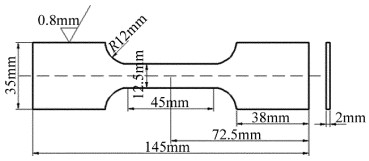
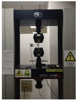
    本文中选用经典的Johnson-Cook(J-C)模型来描述材料的动态响应[18],材料的弹性模量通过标准静态拉伸实验测定,拉伸试样具体尺寸如图 1所示。拉伸试样的实物图如图 2所示。拉伸实验设备采用WDW-100E微机控制电子万能试验机,如图 3所示。其它参量参见参考文献[19],具体取值见表 2

    Figure 1.  Dimensions of tensile specimen

    Figure 2.  Tensile specimen

    Figure 3.  WDW-100E electronic universal testing machine

    parameters density ρ/
    (kg·m-3)
    Posson’s ratio ν elastic modulus
    E/MPa
    A/MPa B/MPa n m C melting point Tm/℃
    value 4680 0.33 115813 1100 590 0.41 0.833 0.0152 1675

    Table 2.  J-C model parameters

    表 2中,AB为系数,n为应变硬化指数,m为温度软化指数,C为应变率敏感系数。

    材料阻尼按下式计算:

    式中,ζ为粘滞阻尼比,大小为0.021;α, β为瑞利阻尼系数,单位分别为s-1和s;ω1, ω2为第1阶和第2阶固有频率,单位为Hz。ω1ω2通过模态计算求得,具体阻尼计算值见表 3

    thickness/mm 1.2 4 6 8 10 15
    α 1971.952 1965.342 1955.802 1641.937 1297.485 847.011
    β 4.47441×10⁻⁷ 4.50093×10⁻⁷ 4.52508×10⁻⁷ 5.37187×10⁻⁷ 6.79875×10⁻⁷ 10.4317×10⁻⁷

    Table 3.  Damping coefficients of compact-tension specimen with different thicknesses

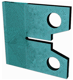
  • 试件具体尺寸如图 4所示,其厚度为4mm。本文中采用图 5所示的有限元模型进行分析。采用的冲击路径如图 6所示。

    Figure 4.  Specimen dimensions

    Figure 5.  Finite element meshing model

    Figure 6.  One-way S-shaped LSP path

    单元采用C3D8R,并对冲击区域细化网格。进行网格敏感性测试后,最终确定表面网格边长Lx=150μm、深度方向边长Lz=100μm作为冲击区域划分网格的标准。

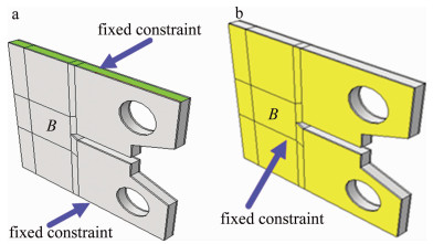
  • 由于采用了不同的冲击方式,考虑真实情况,其边界条件会发生改变。图 7为不同冲击方式下试件的约束情况。双面同时冲击时顶端和底端施加固定约束,B面为冲击面,对面A面也为冲击面;单面冲击时在B面施加固定约束,对面A面为冲击面。

    Figure 7.  Constraint conditions of the model under different impact modes

    本文中选用的冲击压力模型为Fabbro模型[20],其激光冲击峰值压力按下式估算:

    式中,pmax为冲击波峰值压力,单位为GPa;α1为内能转化为热能比例,本文中取为0.1;Z为折合声阻抗, 单位为g·cm-2·s-1I为脉冲激光的平均功率密度, 单位为GW/cm2

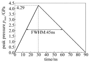
    由相关实验参量[17]可得冲击波压力峰值pmax=4.29GPa。根据ZHANG等人的研究[21],激光冲击强化压力随时间和空间变化规律为:

    式中,r为冲击区域任意位置到光斑中心的径向距离;R为光斑半径;p(t)为冲击压力随时间的变化过程;exp [-r2/(2R2)]为空间分布特性。本文中将采用此压力波空间分布模型进行加载。冲击压力波时间分布模型如图 8所示。其半峰全宽(full width at half maximum,FWHM)按3倍激光器脉宽选取,即为45ns。

    Figure 8.  Relationship between peak pressure and time of the shock wave

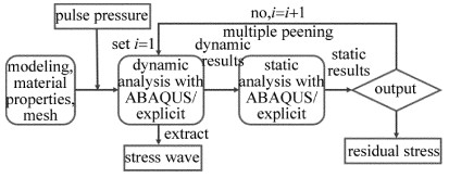
  • 激光冲击强化具有高应变率、高度非线性的特征,属于瞬态冲击动力学范畴[22],在ABAQUS中此种问题一般采用显式积分算法。考虑到材料在冲击处理时会产生大量弹性应变,需进行回弹分析。基于计算成本的考虑,本文中联合使用ABAQUS/Explicit和ABAQUS/Standard两个模块。具体分析流程见图 9

    Figure 9.  Flow chart of finite element analysis

    本文中对时间步长的评价采用稳定极限法,按网格评价中得到的最小单元长度100μm进行计算,此时稳定极限Δtstable=16.5ns。时间步长设置要小于稳定极限,最终确定为11.8ns。关于求解时间,通过能量转化来判定,以大于动能和弹性能均变为0的时间作为求解时间,即为40000ns。

2.   结果分析与讨论
  • 本文中将探索单面冲击和双面冲击下的残余应力分布规律。冲击方式有3种:(1)单面冲击;(2)双面同时冲击;(3)双面顺序冲击。

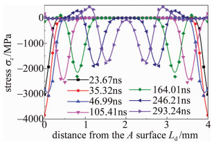
  • 图 10为双面同时冲击应力波结构。图中σz为沿z轴方向,即深度方向的应力; Ld为距冲击表面A的距离。由图可知,应力波在两端同时向内传播,且关于试件中面对称,在246.21ns左右两侧的应力波相遇,之后两侧的应力波在试件中部叠加,使材料中部的应力波相较于单侧冲击时加倍。但此时由于两侧应力波还没到达对面,还没产生反射波,两侧的塑性变形区以及残余应力未受到影响。

    Figure 10.  Stress wave structure of two-side simultaneous LSP

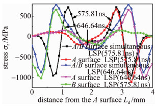
    假定单面冲击作用表面为A面,相对表面为B面。应力波叠加之后各深度处的应力值见图 11。如图 11所示,通过分析应力波传播可知,无论是单面还是双面,应力波均在575.81ns左右到达对面。对于单面冲击,应力波在到达B面后开始发生反射,但反射波只与A面传播过来的入射波进行叠加;而对于双面冲击,应力波在到达B面后,反射波不仅与A面传播过来的入射波进行叠加,还要与B面的入射波进行叠加。下三角特征线与菱形特征线分别为646.64ns时单面冲击A面和B面的应力波结构,而上三角特征线为646.64ns时双面冲击的应力波结构,可发现双面冲击的应力值σdA面冲击应力值σAB面冲击应力值σB的和,即:

    Figure 11.  Stress wave structure of one-side and two-side simultaneous LSP

    由(4)式可知,若σAσB均为正,即均为拉应力,则σd为正值且大于max(σA, σB);若σAσB均为负,即均为压应力,则为负值且绝对值大于max(|σA|,|σB|);若σA, σB一正一负,则σd正负取决于σAσB绝对值大小。通常情况下,应力波结构中的最大压应力要大于最大拉应力,所以σd通常为负,但其绝对值要小于最大压应力绝对值。

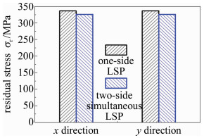
    图 12所示为单面冲击与双面同时冲击稳定后的残余应力场。图中σr表示残余应力。由图可知,单面激光冲击强化获得的x方向和y方向的最大残余应力分别为336.709MPa和337.011MPa,而双面同时激光冲击强化在两个方向均为326.401MPa,即单面冲击获得的残余应力值比双面同时冲击高。这是由于σA为正值而σB为负值,导致σd < σB。单面冲击稳定后会在冲击对面产生拉应力,在冲击表面产生压应力,双面同时冲击相当于利用产生的一部分残余压应力抵消了拉应力,同时又由于应力波的叠加和削弱作用,导致残余应力水平下降。

    Figure 12.  Comparison of maximum residual stress

    图 13所示为y方向应力分布情况。图中σy表示图 14中的y方向残余应力。双面同时冲击在试件厚度方向产生对称的应力分布;单面冲击则会产生拉应力,而不利于抑制裂纹。因此对于薄板而言,提升了一面的断裂韧性,但另一侧的断裂韧性反而下降了。综合考虑而言,双面同时冲击强化效果优于单面冲击。

    Figure 13.  y-direction stress along depth direction

    Figure 14.  Analysis path of residual stress

  • 双面顺序冲击情况下,试件的约束方式与单面冲击相似,先将B面固定而冲击A面,再将A面固定而冲击B面。在冲击表面做如图 14所示的路径。

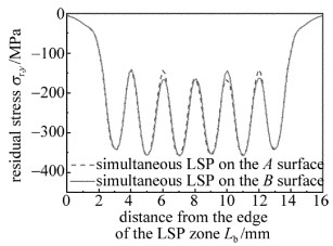
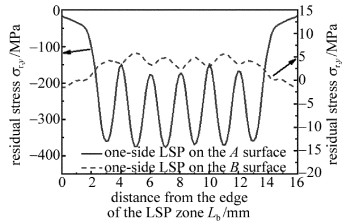
    图 15为双面同时冲击时Py4路径A, B表面残余应力分布情况。图中σr, y表示图 14中所示y方向残余应力,Lb为距冲击区边缘的距离,以下图中相同。由图可知,同时冲击下试件A, B表面y方向残余应力分布基本一致,这说明同时冲击时应力分布具有对称性。图 16为双面顺序冲击时Py4路径A, B表面残余应力分布情况。由图可知,A表面y方向残余应力大于B表面,且应力幅高于B表面。对比同时冲击与顺序冲击情况可发现,顺序冲击下,其最大y方向残余压应力大于同时冲击。这是因为同时冲击时应力波在厚度方向对称分布,两侧面应力波同时存在且同时消失,其应力水平基本一致;另外又由于应力波的反射和叠加导致应力水平小于单面冲击。顺序冲击时,不需考虑应力波的相互作用影响,A面冲击完时的残余应力分布与单面冲击强化效果相同,即在A面为残余压应力面,B面为拉应力,如图 17所示。当进行B面冲击时A面已稳定,B面冲击将会进一步加强A面已形成的残余应力。

    Figure 15.  Residual stress distribution of surface A and surface B on Py4 path under two-side simultaneous LSP

    Figure 16.  Residual stress distribution of surface A and surface B on Py4 path under two-side successive LSP

    Figure 17.  Residual stress distribution of surface A and surface B on Py4 path under one-side LSP

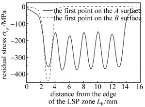
    双面同时冲击与顺序冲击残余应力分布产生差异还存在另一个原因。在B面第1点冲击后,Py1路径AB表面y方向残余应力分布如图 18所示。在B面第2点冲击后,Py1路径A, B表面y方向残余应力分布如图 19所示。对比图 18图 19发现,B面第1点冲击后y方向残余应力要大于A面,且A面残余应力与单面冲击A面时数值相同;当第2点冲击后,Ay方向残余应力值反而迅速增大且最大值与第1点冲击后B面残余应力最大值相近,By方向残余应力值反而减小且与单面冲击A面时数值相近;第3点冲击时A面残余应力值已基本不变,如图 20所示。上述现象说明,在对有限大试件进行冲击强化分析时,不仅要考虑反射波的作用,还需考虑冲击波的横向传播,应力波在试件中的传播表现为复杂的多维平面应变波。

    Figure 18.  Residual stress distribution of surface A and surface B on Py1 path when B surface suffers one point LSP

    Figure 19.  Residual stress distribution of the surface A and surface B on Py1 path when B surface suffers two points LSP

    Figure 20.  Residual stress distribution of surface A and surface B on Py1 path when B surface suffers three points LSP

3.   结论
  • 以双相钛合金TC17为研究对象,采用数值方法分析了单双面激光冲击强化后残余应力场分布规律。

    (1) 单面冲击获得的最大残余应力值比双面冲击高。单面激光冲击强化获得的x方向和y方向的最大残余应力分别为336.709MPa和337.011MPa,而双面同时激光冲击强化在两个方向均为326.401MPa。单面冲击稳定后会在冲击对面产生拉应力,在冲击表面产生压应力;双面同时冲击在试件厚度方向将产生对称的应力分布。单面冲击会由于拉应力的产生而不利于抑制裂纹,因而双面同时冲击强化效果优于单面冲击。

    (2) 双面同时冲击方式下,试件两面的残余应力分布基本一致,顺序冲击时先冲击面残余应力要高于后冲击面,这是由于:同时冲击时两侧应力波会相互同时影响,而顺序冲击时无此现象;有限大试件中冲击波的横向传播会对残余应力的分布造成影响。

Reference (22)

Catalog

    /

    DownLoad:  Full-Size Img  PowerPoint
    Return
    Return