Advanced Search

ISSN1001-3806 CN51-1125/TN Map

Volume 42 Issue 5
Sep.  2018
Article Contents
Turn off MathJax

Citation:

Study on focusing of wideband beam based on metasurface

  • Corresponding author: WANG Jiming, jimingw@nuaa.edu.cn
  • Received Date: 2017-11-16
    Accepted Date: 2017-12-06
  • Meta-surface is optical flat film based on sub-wavelength structure, which can regulate phase, amplitude and polarization of incident beam in sub-wavelength range. In order to replace the traditional surface optical elements, one new type of mata-surface was designed by using the transmission phase regulation theory and the generalized reflection law. Program simulation was carried out and the data of beam focused and regulated by the sub-wavelength structure were obtained. The results show that, when the length of long and short axis of elliptical element of mata-surface is longer, equivalent refractive index of material increases at the same time and the applicable wavelength range increases to 0.7μm~1.2μm. By optimizing the mata-surface structure parameters, phase regulation within wide wave band can be realized, and the optimization of the focused light field can be obtained. To a certain extent, it can replace traditional optical elements to realize optical focusing. The results have some reference value in super-resolution imaging and photolithography. It can simplify the optical path in some special demands that sub-wavelength structure can regulate the beams. Compared with the traditional optical elements, mata-surface has the advantages of thickness.
  • 加载中
  • [1]

    EVLYUKHIN A B, REINHARDT C, SEIDEL A, et al. Optical response features of Si-nanoparticle arrays[J]. Physical Review, 2010, B82(4):045404.
    [2]

    SMITH D R, PENDRY J B, WILTSHIRE M C K. Metamaterials and negative refractive index[J]. Science, 2004, 305(5685):788-792. doi: 10.1126/science.1096796
    [3]

    JAHANI S, JACOB Z. All-dielectric metamaterials[J]. Nature Nanotechnology, 2016, 11(1):23-36. doi: 10.1038/nnano.2015.304
    [4]

    YU N, CAPASSO F. Flat optics with designer metasurfaces[J]. Nature Materials, 2014, 13(2):139-150. doi: 10.1038/nmat3839
    [5]

    MUELLER J P B, RUBIN N A, DEVLIN R C, et al. Metasurface polarization optics:independent phase control of arbitrary orthogonal states of polarization[J]. Physical Review Letters, 2017, 118(11):113901. doi: 10.1103/PhysRevLett.118.113901
    [6]

    DIAO J, YUAN W, YU Y, et al. Controllable design of super-oscillatory planar lenses for sub-diffraction-limit optical needles[J]. Optics Express, 2016, 24(3):1924-1933. doi: 10.1364/OE.24.001924
    [7]

    JIANG X X, WANG J M, HUANG X, et al. Complex amplitude pupil filter based on metasurface with subwavelength slot antenna[J]. Laser Technology, 2017, 41(6):807-811(in Chinese).
    [8]

    LAROUCHE S, SMITH D R. Reconciliation of generalized refraction with diffraction theory[J]. Optics Letters, 2012, 37(12):2391-2393. doi: 10.1364/OL.37.002391
    [9]

    KAMALI S M, ARBABI A, ARBABI E, et al. Decoupling optical function and geometrical form using conformal flexible dielectric metasurfaces[J]. Nature Communications, 2016, 7(5):11618.
    [10]

    KHORASANINEJAD M, CHEN W T, DEVLIN R C, et al. Metalenses at visible wavelengths:Diffraction-limited focusing and subwavelength resolution imaging[J]. Science, 2016, 352(6290):1190-1194. doi: 10.1126/science.aaf6644
    [11]

    YU N, CAPASSO F. Optical metasurfaces and prospect of their applications including fiber optics[J]. Journal of Lightwave Technology, 2015, 33(12):2344-2358. doi: 10.1109/JLT.2015.2404860
    [12]

    PU M, LI X, MA X, et al. Catenary optics for achromatic generation of perfect optical angular momentum[J]. Science Advances, 2015, 1(9):e1500396. doi: 10.1126/sciadv.1500396
    [13]

    SUN Y Y, HAN L, SHI X Y, et al. General laws of reflection and refraction for metasurface with phase discontinuity[J]. Acta Physica Sinica, 2013, 62(10):104201(in Chinese).
    [14]

    YU N, GENEVET P, KATS M A, et al. Light propagation with phase discontinuities:generalized laws of reflection and refraction[J]. Science, 2011, 334(6054):333-337. doi: 10.1126/science.1210713
    [15]

    KILDISHEV A V, BOLTASSEVA A, SHALAEV V M. Planar photonics with metasurfaces[J]. Science, 2013, 339(6125):1232009. doi: 10.1126/science.1232009
    [16]

    SPINELLI P, VERSCHUUREN M A, POLMAN A. Broadband omnidirectional antireflection coating based on subwavelength surface Mie resonators[J]. Nature Communications, 2012, 3(2):692.
    [17]

    ARBABI A, HORIE Y, BALL A J, et al. Subwavelength-thick lenses with high numerical apertures and large efficiency based on high-contrast transmitarrays.[J]. Nature Communications, 2015, 6(5):7069.
    [18]

    DECKER M, STAUDE I, FALKNER M, et al. High-efficiency dielectric Huygens' surfaces[J]. Advanced Optical Materials, 2015, 3(6):813-820. doi: 10.1002/adom.v3.6
    [19]

    LIN D, FAN P, HASMAN E, et al. Dielectric gradient metasurface optical elements[J]. Science, 2014, 345(6194):298-302. doi: 10.1126/science.1253213
    [20]

    ARBABI E, ARBABI A, KAMALI S M, et al. Multiwavelength polarization-insensitive lenses based on dielectric metasurfaces with meta-molecules[J]. Optica, 2016, 3(6):628-633. doi: 10.1364/OPTICA.3.000628
    [21]

    OSKOOI A F, ROUNDY D, IBANESCU M, et al. Meep:A flexible free-software package for electromagnetic simulations by the FDTD method[J]. Computer Physics Communications, 2010, 181(3):687-702. doi: 10.1016/j.cpc.2009.11.008
  • 加载中
通讯作者: 陈斌, bchen63@163.com
  • 1. 

    沈阳化工大学材料科学与工程学院 沈阳 110142

  1. 本站搜索
  2. 百度学术搜索
  3. 万方数据库搜索
  4. CNKI搜索

Figures(11)

Article views(4902) PDF downloads(114) Cited by()

Proportional views

Study on focusing of wideband beam based on metasurface

    Corresponding author: WANG Jiming, jimingw@nuaa.edu.cn
  • Department of Applied Physics, College of Science, Nanjing University of Aeronautics and Astronautics, Nanjing 211106, China

Abstract: Meta-surface is optical flat film based on sub-wavelength structure, which can regulate phase, amplitude and polarization of incident beam in sub-wavelength range. In order to replace the traditional surface optical elements, one new type of mata-surface was designed by using the transmission phase regulation theory and the generalized reflection law. Program simulation was carried out and the data of beam focused and regulated by the sub-wavelength structure were obtained. The results show that, when the length of long and short axis of elliptical element of mata-surface is longer, equivalent refractive index of material increases at the same time and the applicable wavelength range increases to 0.7μm~1.2μm. By optimizing the mata-surface structure parameters, phase regulation within wide wave band can be realized, and the optimization of the focused light field can be obtained. To a certain extent, it can replace traditional optical elements to realize optical focusing. The results have some reference value in super-resolution imaging and photolithography. It can simplify the optical path in some special demands that sub-wavelength structure can regulate the beams. Compared with the traditional optical elements, mata-surface has the advantages of thickness.

引言
  • 传统光学元件利用材料折射率差异或表面变化来实现特定的相位分布,因此其器件体积重量通常较大。近年来提出的亚波长结构电磁调控技术,具有设计灵活、多参量操控和亚波长尺度的精确电磁调制能力等特点[1],在亚波长电磁学、表面等离子体光学、超构材料等多个新兴的领域受到广泛关注。超构材料[2]一般是指典型的基于亚波长结构构建的人工结构材料。当对亚波长结构材料进行深入研究时,可将3维超构材料压缩到2维,如基于等离子体天线、纳米晶体、介质柱等微元的超颖表面[3]。作为一种平面化的结构平面,超表面器件有望在集成光学或微光学系统等特定领域,取代传统的曲面光学组件,实现对光束进行聚焦、偏振调控等[4-7],从而降低系统的复杂程度和提高系统的可靠性。超表面的介质谐振腔须满足以下要求:具有亚波长厚度;相位响应覆盖整个2π范围;各阵列中散射振幅须一样大[8]。在一些新型的超表面在表面基元不变的情况下,同时对整个基底平面进行一些弯折,也可以以此来提高聚焦的效率[9]。并且由于微纳米加工技术的发展,使得超表面的理论、加工及其实际应用得到了快速的发展, 不断有新型超薄超表面的设计和应用也被提出来[10]

    本文中主要工作是构建一个具有亚波长基元结构的超表面,通过调节表面基元结构参量,调控通过的电磁波相位,来达到在较宽的波段上实现光束聚焦的目的。

1.   超表面相位调控理论
  • 超表面实质就是利用带有亚波长分离和空间变化的几何参量的阵列来形成一个随着空间变化的光学响应,以此塑造光的波阵面。根据惠更斯原理,界面上每一个点创建一个球面波,波的干扰形成了新的波阵面[11]。为研究超表面中反射和折射的现象,引入广义反射折射定律[12]

    图 1所示,从A点出发的光线, 经过界面处不同位置CD到达B点, 可以获得相同相移,即光线经ACBADB两种路径的相移量相同,表示为[13]:

    Figure 1.  Schematic of the generalized refraction and reflection law

    式中,k0=2π/λ0, λ0是真空中的波长,θt是折射角;Φ, dΦ分别是两种路径通过界面产生的不连续相位;dx是两点的距离差;nint分别是两个界面的折射率;相位突变量的梯度表示为dΦ/dx,得到广义折射定律:

    同样可以得到广义反射定理[14]

    nint界面上的相位突变量Φ,在x方向以一定梯度分布,即在界面存在相位突变梯度,即dΦ/dx[15]。根据沿界面的波矢的概念,此处折射和反射光束中的波矢等于相位梯度。

    通过调控电磁波通过介质的传输过程中产生的光程差,可以来产生所需电磁波的波前。设此介质折射率为n,当波长为λ0的电磁波在该均匀介质中传输一定的距离d,则此光束积累的传输过程中产生的相位是:

    对于传统的相位型光学元件,为获得所需波前,通常是利用厚度d随空间变化的特点,采取曲面面型来得到相位的调节,但足够的相位差一般需要d变化较大。根据广义折射与反射定律, 可以在厚度不变的情况下,通过改变超表面的结构,来调节等效折射率n。以下使用SiO2基底上的椭圆硅柱阵列结构,通过改变单元结构中的比例,如调整线宽使得排列介质的占空比改变,从而实现传输相位的调节。

2.   基于超表面的聚焦调控
  • 为实现大规模集成处理光路,研究人员已提出多种有效的介质结构来替代透镜[16],但制造困难。为解决金属型超表面的表面损耗问题,ARBABI教授[17]在2015中提出了一种微米厚的高对比超表面,通过在基底上添加圆柱型的柱可以提高光束聚焦的传输效率,但适用波长从1450nm~1550nm。在这之后他们也对于长短比进行了改变,将圆柱型Si柱改为椭圆型Si柱,但是其适用范围局限在近红外915nm处。因此作者在其工作基础上,进一步改进基元结构,通过调整基元长短比和之间间距,用以实现较宽波带下的相位调控,以增大可适用的波长范围。

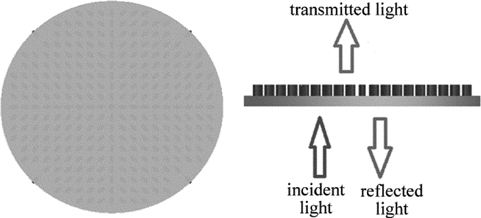
    图 2是超表面的示意图以及当入射线偏振光垂直照射以后的结果。将高折射率介质散射体定位在周期性亚波长2维晶格上的超表面,详细结构如图 3所示。基底是高度为0.65μm的SiO2,表面的基元为高度0.715μm的椭圆型Si柱。每个椭圆型Si柱之间横向间距是0.5μm;纵向和斜向分布Si柱间距是0.4μm~0.7μm;排列分布时中心的基元相对密集,而越往边缘分布的相应稀疏;而且4个象限的长轴倾角是在30°~60°对称分布,共是291个椭圆型Si柱单元。而其高指数导致散射体之间的相互作用可以忽略不计,所以光在每个位置的发散主要由每个基元决定[18],而不是相互之间的耦合产生的共同作用[19]。作者通过模拟确定了4个象限的长轴倾角并且与中心对称分布,这样只需要改变基元椭圆的线宽控制传输相位,已知可实现对聚焦位置的改变[20]

    Figure 2.  Metasurface's cross-sectional schematic

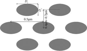
    Figure 3.  Schematic of ellipse Si column

    根据超表面相位调控理论,设计的结构通过改变线宽以调整等效折射率,从而改变传输相位。近几年,国内外研究人员主要使用时域有限差分法(finite-difference time-domain,FDTD)Solutions软件[21]对全介质型的超表面进行仿真研究,来分析各波段电磁波与具有亚波长典型尺寸复杂结构的相互作用,报道的仿真结果与实验结果相吻合。作者在此用FDTD Solutions软件对结构中DxDy改变对光束会聚的影响、在不同波长下聚焦结果的不同做了仿真分析。

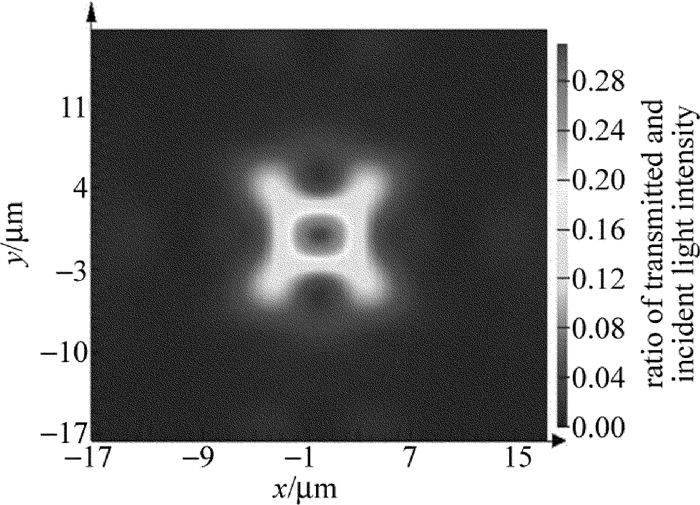
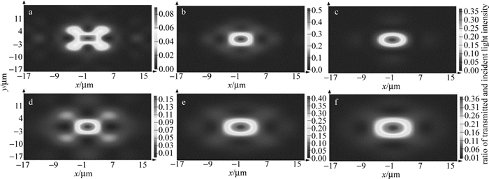
  • 对波长λ=915nm、偏振方向为x方向的平面光通过超表面进行模拟,在结构后聚焦位置f=40μm处对通过的光线进行分析, 结果如图 4所示。色柱是焦平面光强和入射光强的比值。从图中可以看出,当Dx=0.1μm,Dy=0.2μm时,中心光斑直径约为4.2μm,透射率为46.3%;当Dx=0.15μm,Dy=0.3μm时,中心光斑直径约为4.4μm,透射率为41.9%;当Dx=0.1μm,Dy=0.3μm时,边缘位置光束没有收束到中心区域,在Dx=2μm,Dy=0.3μm也可以看出光斑直径变大。在Dx一定时,增大Dy的长度,线宽对应增大,导致传输相位变大,在边缘位置这种相位的改变没有靠近中心区域明显,导致没有收束;同理在Dy一定时,改变Dx可以得出相应结论。所以在经过一系列调试,当DxDy直径偏小时,光线在亚红外附近聚焦效果比较好,相对光斑直径较小。

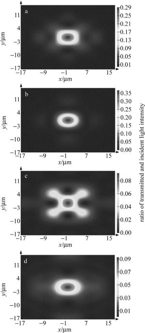
    Figure 4.  Light intensity distribution at different Dx and Dy (λ=915nm, f=40μm)

  • 可以从图 5看出,除了主聚焦点,旁边还分散着4个光强偏弱的聚焦点。这说明了由于波长小于椭圆非晶Si柱的间距,导致光束在通过部分区域时,周期性对称分布的波阵面相互未发生干涉,使得每一个区域单独聚焦形成了分别的聚焦点。

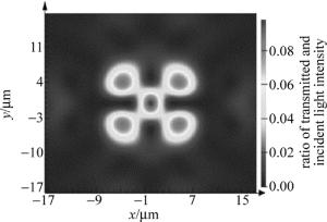
    Figure 5.  Light intensity distribution in focal volume(λ=700nm, f=40μm)

    λ=720nm时,可以从图 6看出,旁边的微弱的聚焦点收束到了中心区域,使得聚焦效果变好,光斑大小变小,但是周围区域仍有光束未收束到中心区域。

    Figure 6.  Light intensity distribution (λ=720nm, f=40μm)

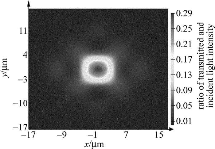
    随着波长进一步增大,单一光束在通过每个区域椭圆非晶Si柱之后,互相的干涉变强,使得光束汇聚作用变强,如图 7所示。

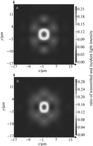
    Figure 7.  Light intensity distribution

    图 8所示,当波长进一步变大时,光斑又开始变大,汇聚效果不明显,尤其在超过波长915nm之后,因为部分区域光束波长已经近似等于椭圆非晶Si柱的规格,使得光束并没有通过散射体进行中心方向偏折,导致汇聚效果失效。

    Figure 8.  Light intensity distribution(λ=915nm)

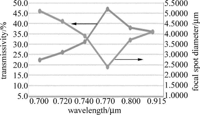
    图 9中横坐标代表着入射光的波长, 左边的纵坐标代表着透射率,而右边的代表了相应的聚焦直径。可以看出, 随着波长的逐步增加,透射率也随之升高,波长平均增加50nm,透射率平均提高14%,聚焦的效果也最好。在λ=770nm附近汇聚效果最好,然后光斑开始变大,透射率下降。

    Figure 9.  Relationship of transmissivity, focal spot diameter and wavelength(Dx=0.1μm, Dy=0.2μm)

  • 图 10中可以看出,当λ=0.7μm时,聚焦点附近还依然有比较强的光通过,说明光线还没有完全汇聚,依然存在微弱的次聚焦点;当λ=0.8μm~1.0μm时,结构对于光束的汇聚效果达到最强,随着波长进一步扩大,因为部分区域光束波长已经近似等于椭圆非晶Si柱的规格,某些光束并没有通过散射体进行中心方向偏折,相互干涉变弱,使光束呈现扩散趋势。

    Figure 10.  Light intensity distributions at different wavelengths(Dx=0.15μm, Dy=0.3μm)
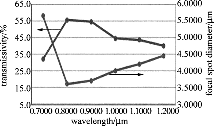
    图 11中可以看出, 随着波长从0.7μm的逐步增加,透射率也随之升高。λ在0.8μm~0.9μm附近汇聚效果最好,透射率也在50%以上,然后光斑大小开始逐渐变大,透射率随之下降,不过下降并不明显。

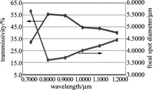
    Figure 11.  Relationship of transmissivity, focal spot diameter and wavelength(Dx=0.15μm, Dy=0.3μm)

    对比第1组的DxDy,当把Dx=0.1μm和Dy=0.2μm增大为Dx=0.15μm和Dy=0.3μm,发现适用的波长范围变大,并且适用的波长增大到了红外。结合第1节中的理论分析,当增加了超表面上椭圆基元的长轴、短轴,因为Si柱的折射率大于SiO2基底的折射率,所以改变了占空比之后,等效折射率随之变大,相应的适用波长也要随之增加。当通过的光束的波长相对较大时,DxDy相应也要增大与之对应,并且可以推测相应的椭圆结构之间相应的间距将会变短,从而影响聚焦的焦场分布和焦距大小。

    综上所述,每一个微型Si柱都会对光的发散产生影响。因为外围的每个基元随着与中心距离增大,相应的排列分布的更加稀疏,所以等效折射率在外围周边相应较小。而在中心区域,基元排列的较为密集,因此等效折射率较大。超颖表面等效为一个凸透镜,在保持d不变的情况下,通过改变折射率n来控制传输型相位,以实现光束聚焦。由于器件厚度d可远小于波长,当线宽不变时,主要是占空比所对应的等效折射率和波长共同贡献传输相位的改变,当入射光波长在一定范围变化时,由于调整了基元在基底的排列分布,使得等效折射率在传输相位中占主要影响作用。因此,可以在较宽波带范围内,通过调整线宽,来控制传输相位,以此实现光束聚焦。

3.   结论
  • 基于超颖表面相位调控理论,研究了超表面的光束聚焦调控的可行性。设计了一种基于光束聚焦的超颖表面,通过调整线宽(改变椭圆型Si柱的DxDy),可以控制相应超表面表面的等效折射率,从而改变穿过电磁波的传输相位,并且分析了不同波长下的聚焦特性。研究结果表明,通过优化超表面结构参量,可实现在宽波带范围内的相位调控,进而获得聚焦光场的优化。这种超表面在宽波段范围内实现较理想的光束聚焦,在超分辨率成像及光刻等方面有一定参考价值。

Reference (21)

Catalog

    /

    DownLoad:  Full-Size Img  PowerPoint
    Return
    Return