Advanced Search

ISSN1001-3806 CN51-1125/TN Map

Volume 42 Issue 4
May  2018
Article Contents
Turn off MathJax

Citation:

Optical axis stabilization technology based on FSM on a vehicle platform

  • Received Date: 2017-09-26
    Accepted Date: 2017-11-03
  • In order to meet application requirements of optical axis stabilization on a vehicle platform, compositions of the optical axis stabilization system were introduced and selection requirements of the driver of a fast steering mirror (FSM) were analyzed. With piezoelectric ceramics actuators as the drivers for the FSM, modal analysis and mechanical simulation of the FSM were carried out and the structure design was optimized. Using the position of centroid detected by high frequency camera as feedback signal, high speed image processing was made with field-programmable gate array, and a FSM for optical axis stabilization based on vehicle platform was developed. Performance parameters of the FSM were tested. After integration test, it is found that the resolution is about 0.4μrad and the bandwidth of the closed loop is more than 100Hz. With the car running at 40km/h on a three-level road, with the FSM controlled by the central computer in unattended mode, the root-mean-square jitters on x and y axes of the closed loop decreases 3.6 and 2.1 times of that of the open loop respectively. The suppression effect of optical axis jitter within 20Hz is obvious and preferable test result is obtained. The system has characteristics of high bandwidth, high accuracy and high stability, and plays an important role in the optical axis stabilization on a vehicle platform.
  • 加载中
  • [1]

    XU X X, GAO Y G, YANG H B, et al. Large-diameter fast steering mirror on rigid support technology for dynamic platform[J]. Optics and Precision Engineering, 2014, 22(1):117-124(in Chinese). doi: 10.3788/OPE.
    [2]

    WANG H Q, WANG W G, XU X X, et al. Solution of correcting values on laser beam directing of fast steering mirror for mobile vehicle[J]. Optics and Precision Engineering, 2016, 24(9):1399-1406(in Chinese).
    [3]

    GAO P F, HU Zh W, DAI S. Study on the application of fast-steering mirror in astronomical instruments[J]. Acta Astronomica Sinica, 2016, 57(3):336-343(in Chinese).
    [4]

    JIANG W H, ZHANG Y D, RAO Ch H, et al. Progress on adaptive optics of institute of optics and electronics, Chanese Academy of Sciences[J]. Acta Optica Sinica, 2011, 31(9):0900106(in Chinese). doi: 10.3788/AOS
    [5]

    BULLARD A, SHAWKI I. Responder (R) fast steering mirror[J]. Proceedings of the SPIE, 2013, 8836:8836-01.
    [6]

    MA J G, TANG T. Review of compound axis servomechanismtre tracking control technology[J]. Infrared and Laser Engineering, 2013, 42(1):218-227(in Chinese).
    [7]

    GUO A L, ZHU H D, YANG Z P. et al. Deformable mirror control algorithm based on the phase correction at the actuator position[J]. Acta Optica Sinica, 2013, 33(3):0311001(in Chinese). doi: 10.3788/AOS
    [8]

    LI L, DONG W W, SHI P. et al. Thermal effect of high power Yb:YAG microchip solid-state laser[J]. Laser Technology, 2010, 34(1):8-12(in Chinese).
    [9]

    MA Z R, WEI Y T, FENG G Y. Theoretical analysis of the beam quality of tow-side-pumped symmetrically transverse flow liquid lasers[J]. Laser Technology, 2011, 35(4):543-546(in Chinese).
    [10]

    DING K, HUANG Y M, MA J G, et al.The error adaptive feedforwrd composite control of fast steering mirror[J]. Chinese Journal of Lasers, 2011, 38(7):1-6(in Chinese).
    [11]

    XIANG S H, CHEN S H, WU X, et al. Research on novel piezoelectric fast steering mirror[J]. Chinese Journal of Lasers, 2009, 36(6):208-212(in Chinase).
    [12]

    WASSON S, MORGAN D F, ECKELKAMP-BAKER D. Embedded FPGA platform for fast steering mirror and optical inertial reference unit application[J].Proceedings of the SPIE, 2011, 8052:80520Q. doi: 10.1117/12.884139
    [13]

    TIAN F Q, LI K Y, WANG Y, et al. Adaptive backstepping sliding mode control of fast steering mirror driven by piezoelectric actuator[J]. High Power Laser and Particle Beams, 2014, 26(1):011011(in Chinese). doi: 10.3788/HPLPB
    [14]

    YIN T.Structure design of shafting fast steering mirror width flexible bearing[J]. Electro-Optic Technology Application, 2012, 27(3):22-25(in Chinese).
    [15]

    LIU Ch F, JIA J J, LI D Y, et al. Structure design and analysis of a double-sided fast steering mirror[J]. Mechanical Science and Technology for Aerospace Engineering, 2015, 35(8):1213-1218(in Chinese).
    [16]

    WANG H J, YANG W Sh, BAO Q L. Sensor fault detection of a fast steering mirror[J]. Opto-Electronic Engineering, 2016, 43(3):46-51(in Chinese).
    [17]

    LI G H, YANG Y, HE Zh W, et al. High accuracy optical axis stable control in beam system of four lasers[J].High Power Laser and Particle Beams, 2014, 26(3):031009(in Chinese). doi: 10.3788/HPLPB
  • 加载中
通讯作者: 陈斌, bchen63@163.com
  • 1. 

    沈阳化工大学材料科学与工程学院 沈阳 110142

  1. 本站搜索
  2. 百度学术搜索
  3. 万方数据库搜索
  4. CNKI搜索

Figures(14)

Article views(4899) PDF downloads(273) Cited by()

Proportional views

Optical axis stabilization technology based on FSM on a vehicle platform

  • 1. Key Laboratory of Science and Technology on High Energy Laser, China Academy of Engineering Physics, Mianyang 621900, China
  • 2. Institute of Applied Electronics, China Academy of Engineering Physics, Mianyang 621900, China

Abstract: In order to meet application requirements of optical axis stabilization on a vehicle platform, compositions of the optical axis stabilization system were introduced and selection requirements of the driver of a fast steering mirror (FSM) were analyzed. With piezoelectric ceramics actuators as the drivers for the FSM, modal analysis and mechanical simulation of the FSM were carried out and the structure design was optimized. Using the position of centroid detected by high frequency camera as feedback signal, high speed image processing was made with field-programmable gate array, and a FSM for optical axis stabilization based on vehicle platform was developed. Performance parameters of the FSM were tested. After integration test, it is found that the resolution is about 0.4μrad and the bandwidth of the closed loop is more than 100Hz. With the car running at 40km/h on a three-level road, with the FSM controlled by the central computer in unattended mode, the root-mean-square jitters on x and y axes of the closed loop decreases 3.6 and 2.1 times of that of the open loop respectively. The suppression effect of optical axis jitter within 20Hz is obvious and preferable test result is obtained. The system has characteristics of high bandwidth, high accuracy and high stability, and plays an important role in the optical axis stabilization on a vehicle platform.

引言
  • 在车载光学系统中,一般会采取钢丝弹簧或气浮平台等措施对光学平台进行主动或被动减震,以减小振动或冲击对系统设备及光束传输的影响[1-2]。由于平台内部光学元件热效应、光束传输中大气湍流、环境噪声以及行车中路面不平和发动机的抖动等条件的影响[3-8],在接收系统中会造成光斑抖动、成像模糊、光束质量变差[9],在发射系统中,会造成目标上光斑漂移、瞄准精度差,因此需要在光路中设置抑制光轴抖动的器件,提高光轴稳定性[4, 6]。电调镜具有光轴调节的功能,但精度不高,调节速度或带宽较低,难以对光轴进行实时稳定,而快反镜无疑是抑制光轴抖动的最佳选择[10-14],它体积小、谐振频率高、响应速度和闭环带宽高,同时可以对光轴进行实时闭环稳定,在激光传输、天文观测以及跟瞄等光学系统中,得到了广泛的应用[4, 6, 10]

    在国外,德国PI公司是微位移和微驱动领域的先驱,该公司采用自产的压电陶瓷结合线性可变差动变压器(linear variable differential transformer, LVDT)或应变片作为反馈元件,研制了大量应用于不同环境的快反镜;美国NewPort公司采用音圈电机作为驱动器,光电二极管作为反馈元件,研制出不同型号的快反镜;英国Queensgate公司采用压电陶瓷研制的快反镜在精密定位方面有较好的应用。在国内,中国科学院光电技术研究所率先从事快反镜研究工作,从20世纪八、九十年代至今,已生产出大量应用于激光通信、天文观测以及跟瞄系统中的快反镜,取得了较好的科研成果[4];另外,在科研院所和高校中,中国科学院长春光学精密机械与物理研究所、中国科学院安徽光学精密机械所、中国科学院西安光学精密机械机所以及哈尔滨工业大学、北京航空航天大学、重庆大学等单位,对快反镜的研究与应用都取得了不错的成绩[4, 6, 10, 14-16]。中国工程物理研究院应用电子学研究所开展了近15年的快反镜技术研究与应用,目前已具备大口径、高带宽、高精度等不同等级快反镜的研制能力[17]

    鉴于车载平台光轴稳定应用需求的特点,作者针对性地开展适用于车载环境的快反镜光轴稳定技术研究,包括驱动器的选型、布局方式,在结构设计中,重点考虑车载环境条件下快反镜抗震动冲击的能力,通过仿真分析,提高快反镜的固有频率,同时,采用高速图像处理和比例-积分-微分(proportion, integral, derivative, PID)闭环控制算法,研制出适用于车载环境使用的快反镜,对行驶中车载平台的光轴抖动进行闭环控制,达到了光轴稳定的目的。

1.   光轴稳定系统的工作原理
  • 光轴稳定控制系统由快反镜、驱动控制系统和反馈系统三部分组成。快反镜是执行机构,反馈系统为控制系统提供位置反馈信息,控制系统将解算的脱靶量经PID控制传输到驱动系统上进行相应的放大,最终加载到快反镜驱动器上,驱动器的伸缩带动镜面发生偏转,从而对光轴指向进行调节[16]图 1是快反镜工作原理图。图中, PC是个人电脑(personal computer), FSM是快速控制反射镜(fast steering mirror), FPGA是现场可编程门阵列(field-programmable gate array)。

    Figure 1.  Working principle of FSM

2.   驱动器的选择
  • 车载条件下,由于汽车行驶过程中,发动机的抖动以及路面不平等原因产生的振动与冲击,对快反镜自身的结构强度、闭环零点的稳定性以及闭环后光轴的指向精度都提出了较高的要求,而快反镜驱动器的选择与这些指标直接相关。当前,快反镜的驱动器主要有音圈电机和压电陶瓷两种类型,音圈电机的定子和线圈是分离体,相互之间无摩擦直线运动,在快反镜结构设计中,安装反射镜的镜框与安装电机的基座之间始终做不到绝对的刚性连接,这就制约了快反镜闭环带宽的提升,同时,采用音圈电机分离体结构进行驱动的快反镜,汽车行驶中对快反镜造成的振动和冲击影响较大;而压电陶瓷驱动器,加载预紧力之后,将安装反射镜的镜框与快反镜的基座进行刚性连接,其固有频率很容易做到很高,在满足动态范围条件下,这种结构对于车载环境应用需求具有较大的技术优势。为此,作者采用压电陶瓷作为驱动器对快反镜进行驱动。

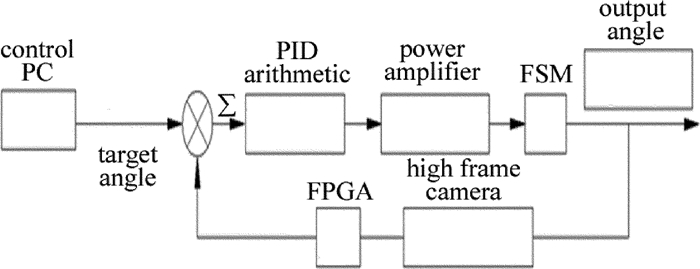
    压电陶瓷自身具有较高的谐振频率,同时分辨率可以达到纳米量级,但迟滞现象比较明显,通过加载预紧力,既可以提高压电陶瓷的抗拉能力,也可以实现驱动器的刚性连接,满足车载环境使用要求。图 2是压电陶瓷预紧力加载前/后的位移-电压曲线。裸陶瓷迟滞18.6%,加载预紧力后迟滞为17.8%,其迟滞百分比变化不大。

    Figure 2.  Hysteresis loop of piezoelectric ceramic with and without loading pretightening force

3.   结构设计及仿真分析
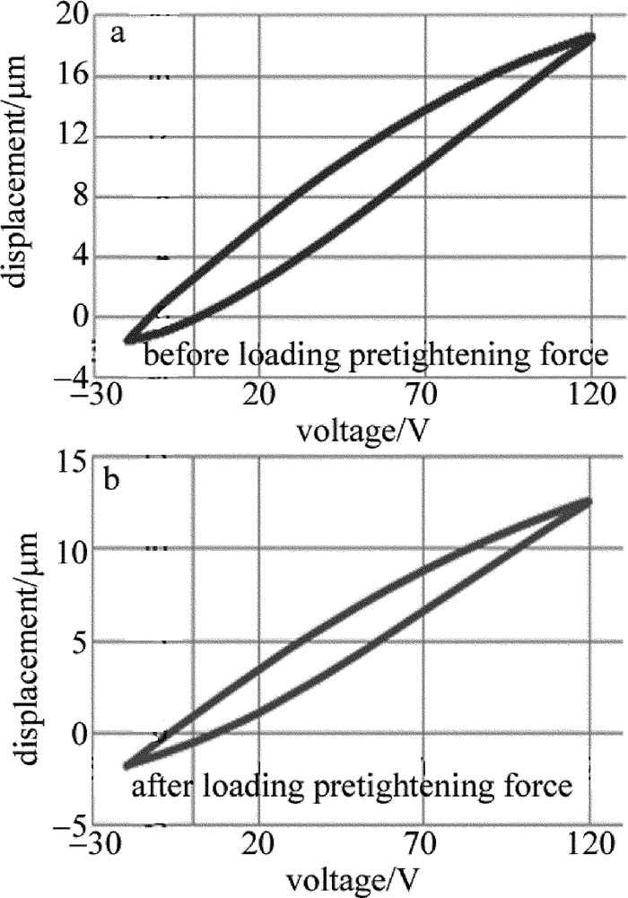
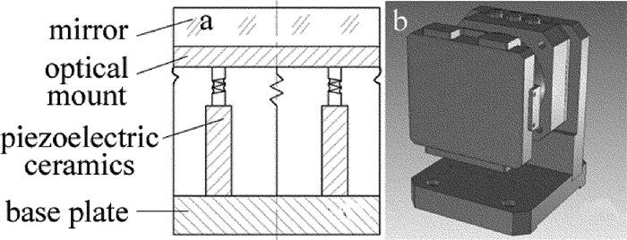
  • 结构设计中,采用四驱动器“十”字正交模式进行结构布局。压电陶瓷加载预紧力后通过柔性铰链将安装反射镜的镜框与基座进行固连,结构件中心处设置柔性限位装置,既确保反射镜绕中心轴转动,又限制反射镜转动过程中发生镜面平移,镜框外围增加弹性结构对反射镜进行辅助支撑。该快反镜结构整体上属于刚性连接,有利于车载环境的应用。图 3是快反镜结构示意图和3维模型。

    Figure 3.  a—structure diagram of a FSM b—3-D model of a FSM

    仿真分析为快反镜结构的优化设计提供帮助。仿真内容包括驱动器驱动能力的仿真,即在驱动器作用下产生的应变是否满足动态范围需求,而产生的内部应力是否小于材料的许用应力,同时仿真还包括模态分析,通过优化设计,提高1阶模态频率。图 4是快反镜应力和应变仿真结果。通过换算,镜面偏转角度为0.347mrad,满足设计指标,最大应力为14.52MPa,集中在驱动器预紧装置的根部,但远小于材料的许用应力,结构强度满足要求。图 5是快反镜1阶~4阶模态振型。1阶模态振型频率为665Hz,是由支架形成的,而2阶模态振型频率为932Hz, 是镜框和反射镜的组合体绕中心轴的转动形成的,通过优化,可以提高其1阶、2阶模态频率。

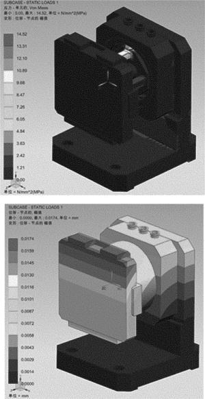
    Figure 4.  Stress/strain simulation results of a FSM

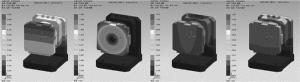
    Figure 5.  1st~4th order modes of a FSM

4.   闭环控制的实现
  • 快反镜工作在闭环模式下,采用FPGA硬件对其进行闭环控制。高帧频互补金属氧化物半导体(complementary metal-oxide semiconeluctor, CMOS)相机320× 510靶面帧频为2033frame/s,光斑图像通过两路Camera Link接口传输至FPGA板卡进行高速图像处理,计算的质心位置用作闭环反馈信号来源,目标位置与质心位置的偏差形成的脱靶量经PID控制模块进行处理,其控制量经LVDS传输协议送入到高压放大器中进行相应的放大并加载到压电陶瓷上,驱动反射镜偏转从而实现闭环控制。采用硬件闭环,从质心计算到高压加载,耗时小于82μs,跟采用上位机进行闭环比较(约3ms),流程时间大幅提高,有利于提高快反镜的闭环带宽。实际应用中,总控向快反镜控制系统下发控制指令,快反镜执行相应的开闭环动作,实现无人值守。图 6是FPGA高速图像处理卡和高压放大器实物。

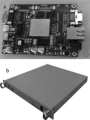
    Figure 6.  a—FPGA high speed image processor b—high-voltage amplifier

5.   性能测试
  • 快反镜的性能参量包括开环响应频率、动态范围、执行精度以及闭环带宽等。图 7是快反镜性能测试原理框图和测试现场。平行光经反射镜、快反镜及缩束系统后入射到相机靶面,PC机通过网口与FPGA连接并发送相关的测试指令,高帧频CMOS相机通过两路Camera Link接口将图像传输给FPGA进行高速图像处理并经PID解算后通过LVDS传输协议传输到高压放大器,放大后的控制电压加载到快反镜上,从而对其相关性能参量进行测试。

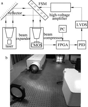
    Figure 7.  a—test diagram for a FSM b—picture of performance testing

    将快反镜闭环以后,以目标像素指令的方式对快反镜进行动态范围和线性度测试。图 8是快反镜动态范围测试曲线。x轴和y轴动态范围均大于0.6mrad,与设计指标相符,且线性度较好。

    Figure 8.  x/y axis dynamic range curve of FSM

    快反镜闭环以后,光斑质心抖动量即为闭环残差;闭环状态下发送较小的目标像素指令让快反镜执行小角度偏转,当无法明显区分质心曲线的变化时,即达到了快反镜的分辨率极限。图 9是快反镜闭环残差和分辨率测试曲线。从曲线上可以看出,快反镜闭环后,质心抖动量小于0.95μrad/峰谷值,均方根在0.1μrad左右,而快反镜分辨率约0.4μrad。

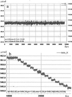
    Figure 9.  a—residual curve of closed loop of a FSM b—resolution curve

    图 10是快反镜xy轴频谱分析曲线。从图上可以看出,快反镜闭环带宽在100Hz以上,其中32Hz处的“冒尖”现象是光源自身产生的。

    Figure 10.  Spectrum analysis curve on x/y axis of a FSM

    开环响应频率的测试,是通过高压放大器给快反镜加载开环正弦电压,用光电二极管接收快反镜反射的回光,用示波器同时采集了两路信号来实现的。图 11是示波器采集到的两路信号。其中下面的曲线是控制系统的指令曲线,指令频率为3.145kHz,上面的曲线是光电二极管的探测到的光电转换信号,即快反镜的响应曲线。从图上可以看出,光电二极管的回光信号良好,无失真现象,快反镜的开环响应频率达到了3kHz以上。

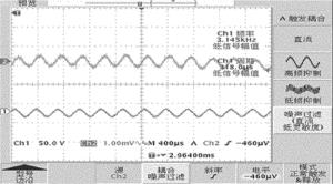
    Figure 11.  Open loop response frequency test of a FSM

6.   系统集成联调
  • 在车载平台上,全系统进行了集成联调。实验中,汽车以40km/h在行驶于三级公路上,上位机发送控制指令,FPGA硬件及控制系统执行相应的命令,快反镜实现相关开闭环任务。图 12x轴开/闭环曲线,图 13y轴开/闭环曲线。从图 12图 13可以看出,快反镜x轴质心抖动均方根从8.33μrad减小到2.26μrad,y轴从18.67μrad减小到8.89μrad,从抖动幅值来看,x轴减小3.6倍,y轴减小2.1倍。

    Figure 12.  Open/closed loop curve on x axis of a FSM

    Figure 13.  Open/closed loop curve on y axis of a FSM

    对汽车行进中快反镜开闭环进行了频谱分析。图 14是快反镜x轴和y轴频谱曲线,从曲线可以看出,快反镜对20Hz以内的光轴抖动抑制效果明显。

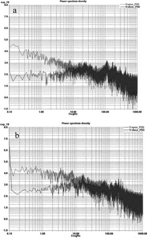
    Figure 14.  Spectrum curve on x axis and y axis of a FSM

7.   结论
  • 基于车载平台光轴稳定的应用需求,开展了压电陶瓷快反镜光轴稳定技术研究,成功研制出刚性连接的快反镜,其分辨率约0.4μrad,闭环带宽大于100Hz。采用FPGA硬件模块对快反镜进行闭环控制,在三级公路上汽车以40km/h行驶时,由总控对快反镜进行控制,快反镜闭环后,x轴光轴抖动均方根值减小3.6倍,y轴减小2.1倍,同时,对系统20Hz以内的频率进行了有效抑制,取得了较好的实验效果,为车载平台的光轴稳定起到了重要作用。

Reference (17)

Catalog

    /

    DownLoad:  Full-Size Img  PowerPoint
    Return
    Return