Advanced Search

ISSN1001-3806 CN51-1125/TN Map

Volume 42 Issue 3
Mar.  2018
Article Contents
Turn off MathJax

Citation:

Optimization of technology parameters for fracture splitting grooves of connecting rods fabricated by pulse fiber laser

  • Corresponding author: WANG Guan, wangguan@gdut.edu.cn
  • Received Date: 2017-06-16
    Accepted Date: 2017-09-08
  • In order to obtain the optimal cutting quality of fracture splitting groove on connecting rod made of new material 36MnVS4, experimental study and theoretical analysis of crack groove fabricated by laser cutting were investigated through orthogonal experimental method. Geometric dimensions such as depth, width, opening angle and curvature radius of fracture splitting groove produced by laser cutting were measured and calculated by laser confocal microscope, respectively. In addition, microstructure and thickness of heat affected zone on the bottom of crack groove were observed and measured by adopting scanning electron microscope. The effects of laser peak power, pulse width, cutting speed and pulse frequency on geometric dimensions of fracture splitting groove were analyzed by using range analysis method. As a result, the optimal parameter combination of cutting fracture splitting groove were found out. The results show that, the depth of heat affected zone on the bottom of crack groove is less than 100μm and there exist micro cracks and pores. The investigated parameters have less impact on the width, opening angle and curvature radius of fracture splitting groove, but have large effect on depth. Moreover, laser peak power and pulse width exert great influence on depth of crack groove, while cutting speed and pulse frequency have little effect on it. The optimal parameters exist with cutting speed of 1.0m/min, laser peak power of 700W, pulse frequency of 1000Hz and pulse width of 50μs. The study is of great importance for actual production.
  • 加载中
  • [1]

    KOU Sh Q, WANG J W, JIAN X X, et al. YAG laser cutting on sharp fracture splitting notch of connecting rod[J]. Optics and Precision Engineering, 2010, 18(6): 1340-1346(in Chinese).
    [2]

    ZHENG Q F. Research on laser processing fracture splitting groove technologyand automation equipment for engine connecting rod[D]. Changchun: Jilin University, 2011: 6-8(in Chinese).
    [3]

    YANG H Y. Numerical simulation of connecting rod fracture processand analysis on main fracture splitting defects[D]. Changchun: Jilin University, 2014: 9-10(in Chinese).
    [4]

    ZHAO Y. Study on parameters of connecting rod fracture splitting basedon fracture after small scale yielding and its application[D]. Changchun: Jilin University, 2011: 53-60(in Chinese).
    [5]

    YANG Q T. Multi-scale simulation study on propagation of connecting rod crack by wire cut electrical discharge machining[D]. Guangzhou: Guangdong University of Technology, 2016: 10-20(in Chin-ese).
    [6]

    WANG J W. Numerical simulation and experimental study on pulsed laser processing fracture pplitting notch of con-rod/crankcase bearing block[D]. Changchun: Jilin University, 2011: 89-105(in Chin-ese).
    [7]

    YANG Sh H, ZHANG Zh Q, KOU Sh Q, et al. Technological parameters in the laser cutting process of starting notch of connecting rod[J]. Journal of Harbin in Institute of Technology, 2009, 41(1):126-130(in Chinese).
    [8]

    SUN J G, LI Sh, HE Zh Y, et al. Study on orthogonal processing experiment of light absorbing coatings for laser micro-dimple[J]. Laser Technology, 2016, 40(6): 907-911(in Chinese).
    [9]

    ZHENG Q F, YANG Sh H, DENG Ch P, et al. Manufacture of connecting-rod initial splittingnotch by Nd:YAG solid laser[J]. Optics and Precision Engineering, 2010, 18(1): 142-147(in Chinese).
    [10]

    LIU Z Y, WEI X, XIE X Zh, et al. Experimental study about micro texture on tool surface processed by UV laser ceramic[J]. Laser Technology, 2016, 40(4): 550-554(in Chinese).
    [11]

    ZHENG L M. Research on key technologies and equipment development of engine connecting rod fracture splitting[D]. Changchun: Jilin University, 2012: 25-40(in Chinese).
    [12]

    ZHANG Zh Q. Numerical analysis and experimental study on influencing factors of splitting process of engine connecting rod[D].Changchun: Jilin University, 2011: 89-105(in Chinese).
    [13]

    LIU P, LI W Zh, WEI Y Sh, et al. Development of fracture splitting connecting rod made of mid-carbonand microalloyed steel without quenching and tempering[J]. Journal of Iron and Steel Research, 2015, 27(1):46-50 (in Chinese).
    [14]

    JIAO J, GUO J F, WANG L, et al. Research of the form and growth of crack of in hot affected zonefor drill by pulsed CO2 laser cutting[J]. Metallurgical Equipment, 2012, 6(3):17-21(in Chinese).
    [15]

    LI F. The experimental research of laser processing for typical material fracture splitting notch[D]. Changchun: Jilin University, 2007: 40-50(in Chinese).
    [16]

    WANG X H. Iron castings temperature field numerical analysis by laser cutting the stress-raising groove[D]. Changchun: Jilin University, 2010: 40-60(in Chinese).
  • 加载中
通讯作者: 陈斌, bchen63@163.com
  • 1. 

    沈阳化工大学材料科学与工程学院 沈阳 110142

  1. 本站搜索
  2. 百度学术搜索
  3. 万方数据库搜索
  4. CNKI搜索

Figures(7) / Tables(5)

Article views(7172) PDF downloads(237) Cited by()

Proportional views

Optimization of technology parameters for fracture splitting grooves of connecting rods fabricated by pulse fiber laser

    Corresponding author: WANG Guan, wangguan@gdut.edu.cn
  • 1. School of Electromechanical and Engineering, Guangdong University of Technology, Guangzhou 510006, China
  • 2. Guangdong Sihui Shili Connecting Rod Co. Ltd., Sihui 526200, China

Abstract: In order to obtain the optimal cutting quality of fracture splitting groove on connecting rod made of new material 36MnVS4, experimental study and theoretical analysis of crack groove fabricated by laser cutting were investigated through orthogonal experimental method. Geometric dimensions such as depth, width, opening angle and curvature radius of fracture splitting groove produced by laser cutting were measured and calculated by laser confocal microscope, respectively. In addition, microstructure and thickness of heat affected zone on the bottom of crack groove were observed and measured by adopting scanning electron microscope. The effects of laser peak power, pulse width, cutting speed and pulse frequency on geometric dimensions of fracture splitting groove were analyzed by using range analysis method. As a result, the optimal parameter combination of cutting fracture splitting groove were found out. The results show that, the depth of heat affected zone on the bottom of crack groove is less than 100μm and there exist micro cracks and pores. The investigated parameters have less impact on the width, opening angle and curvature radius of fracture splitting groove, but have large effect on depth. Moreover, laser peak power and pulse width exert great influence on depth of crack groove, while cutting speed and pulse frequency have little effect on it. The optimal parameters exist with cutting speed of 1.0m/min, laser peak power of 700W, pulse frequency of 1000Hz and pulse width of 50μs. The study is of great importance for actual production.

引言
  • 连杆裂解加工是一种新型连杆加工技术,其采用裂解形成的3维凹凸断裂面代替传统的加工接合面,保证了接合处的精确配合,具有工序少、成本低、效率高、加工质量好、装配精度高、承载能力强等优点,已成为连杆加工的主要方向[1]。连杆裂解加工首先需要在连杆大头孔内侧柱面预制对称裂解槽,裂解时利用裂解槽根部位置形成的应力集中使连杆在预定的位置几乎不产生塑性变形的情况下快速裂解。因此,裂解槽的预制是连杆裂解加工的技术关键[2]。目前,裂解槽的加工方法主要有机械拉削、线切割和激光切割等。机械拉削刀具磨损后,裂解槽根部曲率半径增大,加工深度变浅,导致裂解不稳定;线切割加工精度低、生产效率低;激光加工具有效率高、精度高、无污染等优点,已成为目前最先进的工艺[3]

    连杆裂解槽属于窄缝盲槽,裂解加工对裂解槽加工精度和切口质量要求很高。激光切割是一个多因素共同作用的过程,峰值功率、脉冲宽度、脉冲频率和切割速率等参量都会影响裂解槽的切割质量。不同的切割参量组合对裂解槽的质量影响不一,因此研究各激光参量对切割裂解槽质量的影响程度,并获得最优参量组合对优化激光切割裂解槽质量、降低连杆裂解废品具有重要的意义[4-5]。现有的研究主要采用单因素法研究了YAG激光切割C70S6连杆裂解槽,对光纤激光切割36MnVS4连杆裂解槽的研究还不够深入,且未考虑多个因素同时作用时对切割质量的影响[6]

    本文中采用无交互作用的正交实验方法,设计了四因素四水平的正交实验表,针对光纤激光切割36MnVS4连杆裂解槽的实验,主要研究峰值功率、脉冲宽度、切割速率和脉冲频率等对裂解槽几何参量和底部微观形貌及热影响区深度的影响程度,并得出激光加工裂解槽的最优实验参量组合。

1.   实验设备、材料及实验方案
  • 预制裂解槽的目的是形成缺口效应,提高应力集中水平,能有效降低裂解载荷,保证连杆在预定位置快速脆性裂解,保证加工质量。如图 1所示,裂解槽的槽深h、槽宽w、曲率半径r和张角α对裂解载荷有直接影响,从断裂效率和裂解质量考虑, 要求裂解槽尖锐、深而窄、张角小, 以提高应力集中系数, 有效降低裂解力, 避免裂解缺陷的出现, 保证连杆裂解加工质量[7]

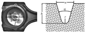
    Figure 1.  Location and parameters of splitting decomposition groove

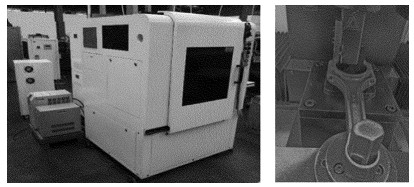
    实验设备采用广东工业大学和广东四会实力连杆有限公司共同研制的胀断连杆激光切槽装备,如图 2所示。该装备采用瑞士ROFIN公司FLBK SC 90/60型号的光纤脉冲激光器,其具体参量见表 1

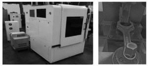
    Figure 2.  Laser curting equipmcnt for processing connecting-rod splitting notch

    laser parameters parameter scale
    laser peak power/W 200~1590
    pulse energy/mJ 0.1~15000
    pulse width/μs 10~5000
    pulse frequency/Hz 0.3~25000

    Table 1.  Laser technical data

    试样选取JL4T18连杆,其材料为非调质中碳合金钢36MnVS4,其主要成分见表 2。连杆毛坯经热锻成型并利用余热进行空气控制冷却,主要为均匀珠光体+铁素体。

    element C S P Si Mn Cr V Al Ni
    w 0.0036 0.00042 0.000007 0.0063 0.0099 0.0024 0.0027 0.00016 0.00011

    Table 2.  Chemical compositions (mass fraction w) of material

  • 脉冲激光加工裂解槽过程中影响切割质量的因素较多,且每个因素有多个水平,此时会优先采用正交实验法。正交实验能在所有因素的不同水平内进行均衡采样,能够在达到较好实验目的同时减少实验次数[8]

    激光加工裂解槽是通过激光脉冲能量使加工位置的金属迅速融化或气化,并利用辅助气体将融化金属从连杆上驱除。脉冲能量Q和脉冲重叠率n是影响激光切割效果的主要因素[9-10]:

    式中, Q为脉冲能量, P为峰值功率, t为脉冲宽度, d为聚焦半径, v为切割速率, f为脉冲频率。

    由(1)式可知, 脉冲能量由峰值功率和脉冲宽度二者共同决定,由(2)式可知, 脉冲重叠率由聚焦半径、切割速率和脉冲频率共同决定。由于实验条件限制,本文中暂不考虑聚焦半径对脉冲重叠率的影响,因此本文中最终选取了峰值功率、脉冲宽度、脉冲频率和切割速率4个参量作为研究的因素,每个因素设置4个水平,切割角度垂直与连杆大头孔内壁且保持不变、辅助气体及离焦量等也保持不变。表 3所示为各个因素在不同水平下的取值。

    level cutting speed/ (m·min-1) peak power/ W pulse frequency/ Hz pulse width/ μs
    1 1.0 600 800 20
    2 1.2 700 900 30
    3 1.4 800 1000 40
    4 1.6 900 1100 50

    Table 3.  Factors and levels of orthogonal experiments

2.   实验结果与讨论
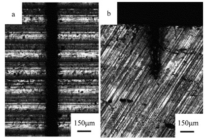
  • 对正交表中每组参量进行3次实验,如图 3所示。通过激光共聚焦显微镜观测裂解槽正面测量裂解槽宽度,观测裂解槽截面测量裂解槽的深度和曲率半径,将3次测量结果取平均值。由于裂解槽曲率半径很小,则可根据下式计算出裂解槽的张角[11]:

    Figure 3.  Morphology of splitting cracks

    裂解槽的深度、宽度、曲率半径的测量平均值及张角的计算结果如表 4所示。

    level cutting speed/ (m·min-1) peak power/ W pulse frequency/ Hz pulse width/ μs notch depth/ μm notch width/ μm radius of curvature/ μm opening angle/ (°)
    1 1.0 600 800 20 250.99 123.88 18.37 27.72
    2 1.0 700 900 30 472.05 154.02 20.21 18.53
    3 1.0 800 1000 40 696.09 184.15 21.01 15.07
    4 1.0 900 1100 50 860.30 187.49 17.56 12.43
    5 1.2 600 900 40 455.18 170.75 32.55 21.24
    6 1.2 700 800 50 692.87 184.15 25.32 15.13
    7 1.2 800 1100 20 518.89 137.27 20.46 15.07
    8 1.2 900 1000 30 632.93 174.11 27.67 15.66
    9 1.4 600 1000 50 522.45 184.18 31.2 19.99
    10 1.4 700 1100 40 579.04 187.49 26.94 18.39
    11 1.4 800 800 30 505.33 160.71 25.10 18.07
    12 1.4 900 900 20 532.27 157.36 23.03 16.81
    13 1.6 600 1100 30 355.50 157.37 25.26 24.96
    14 1.6 700 1000 20 287.88 147.30 20.77 28.70
    15 1.6 800 900 50 840.32 194.19 23.45 13.18
    16 1.6 900 800 40 622.50 187.49 19.28 17.12

    Table 4.  Results of orthogonal experiments

    由实验结果可知:不同的参量组合对裂解槽的宽度、张角和曲率大半径的影响不大。由文献可知:槽深对裂解力的影响最显著,随槽深的增加裂解所需载荷显著减小;曲率半径和张角对裂解载荷也有一定影响,随曲率半径和张角减小裂解所需载荷也越小;槽宽对裂解力的影响最小,随槽宽减小裂解所需载荷降低不明显[12]。由于张角、曲率半径及槽宽变化不大,且不是影响裂解力的主要因素。因此,可只研究不同的参量组合对裂解槽深度的影响程度,并对参量进行优化。采用极差分析法对各个因素在不同水平值下的实验结果进行分析,得到各因素对实验考察指标的影响程度, 结果如表 5所示。

    level cutting speed(A)/ (m·min-1) peak power(B)/ W pulse frequency(C)/ Hz pulse width(D)/ μs
    1 569.86 396.03 517.92 397.51
    2 574.97 507.96 574.96 491.45
    3 534.77 640.16 537.59 588.20
    4 526.55 716.46 578.43 728.99
    range 43.31 320.43 60.51 331.48

    Table 5.  The range of notch depth in different factors and levels

    根据表 5中计算的结果可得到,激光切割参量对裂解槽深度的影响程度由大到小依次为:脉冲宽度>峰值功率>脉冲频率>切割速率。
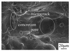
    图 4所示,裂解槽底部凹凸不平且有部分金属融化后未被及时吹除, 而凝结在裂解槽底部表面,形成凝固块。同时存在很多微裂纹和气孔,由于激光切割温度高、时间短,易形成较大的温度梯度从而产生热应力,使金属的变形不均,导致微裂纹的产生。微裂纹可和气孔降低了此处的材料强度,可显著降低裂解力。

    Figure 4.  Scanning electron microscope diagram of the bottom crack

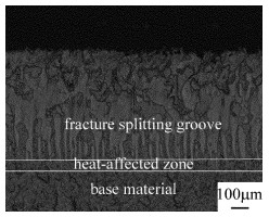
    裂解槽底部存在一定厚度的热影响区,在激光切割时,由于温度过高,且该连杆材料属于中碳钢[13],因此会在高温附近区域形成片状(针状)马氏体[14]。连杆工作时受力情况相当复杂。所以,除了要求连杆具有足够的强度和刚度外,还应保证其具有相应的加工精度。其经激光切槽后,受到激光热作用的组织大部分转变为马氏体,高碳马氏体本身很脆,在撞击时极易产生裂纹,并且由于裂解槽内气孔和微裂纹的存在,这些裂纹和气孔极易成为疲劳裂纹源而导致开裂,必须通过后续机械加工来完全去除这些组织[15-16]。如图 5所示,通过观测连杆裂解后裂解槽的侧面,得到各裂解槽热影响区厚度在70μm左右,为确保能去除热影响区,则取其厚度为100μm。

    Figure 5.  Scanning electron microscope diagram of the lateral crack

    根据连杆加工的要求,连杆裂解后,还需在连杆大头孔内壁进行半精镗、精镗、珩磨等加工工序,其加工余量为700μm。由于热影响区厚度为100μm,故裂解槽深度取600μm为宜。

    A, B, C, D分别表示表 5中的切割速率、峰值功率、脉冲频率和脉冲宽度,字母下标表示字母对应列中的行序号。本文中以裂解槽深度小于且最接近600μm为优化目标。根据表 5的结果,对A, B, C, D每列取小于且最接近600μm的值,得到其值分别为A1, B2, C4, D3,即得到了每个因素下的最优水平,然后将4个因素下的最优水平组合起来,得到最优参量组合为A1B2C4D3,即切割速率为1.0mm/min、峰值功率为700W、脉冲频率为1000Hz、脉冲宽度为50μs。

    图 6为优化前裂解槽的截面形貌。如图 6a所示,在脉冲能量较小时裂解槽深度较浅,会使连杆裂解时裂解力较大,导致连杆大头孔产生较大的塑性变形而出现“失圆”现象,无法满足连杆的精度要求;如图 6b所示,在脉冲能量较大时裂解槽深度太深,使得精加工后热影响区无法去除,甚至裂解槽深度超过加工余量。

    Figure 6.  Sectional view of the crack before optimization

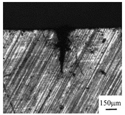
    图 7为优化后裂解槽的截面形貌。此时裂解槽深度符合要求,裂解槽截面呈“V”型,裂解槽尖锐、深而窄、张角小, 可以有效提高应力集中系数, 降低裂解力, 避免裂解缺陷的出现, 保证连杆裂解加工质量。

    Figure 7.  Sectional view of the crack after optimization

3.   结论
  • 通过对光纤脉冲激光切割36MnVS4连杆裂解槽进行正交实验设计, 以切割速率、峰值功率、脉冲频率、脉冲宽度为影响因素,每个因素分别设定4个水平进行实验。

    (1) 激光参量对裂解槽的深度影响较大,对裂解槽的宽度、张角及曲率半径影响不大,加工后槽宽在160μm左右,张角在25°左右,曲率半径在20μm左右。

    (2) 激光参量对裂解槽深度的影响次序为:脉冲宽度>峰值功率>脉冲频率>切割速率。

    (3) 加工后的裂解槽底部存在微裂纹和热影响区,热影响区的厚度小于100μm。

    (4) 通过参量优化后切割出的裂解槽可以获得较好的质量,其最优参量分别是:切割速率为1.0m/min、峰值功率为700W、脉冲频率为1000Hz、脉冲宽度为50μs。

Reference (16)

Catalog

    /

    DownLoad:  Full-Size Img  PowerPoint
    Return
    Return