Advanced Search

ISSN1001-3806 CN51-1125/TN Map

Volume 41 Issue 5
Sep.  2017
Article Contents
Turn off MathJax

Citation:

Design of refractive antennas with coaxial transceiver for wind lidars

  • Received Date: 2016-10-20
    Accepted Date: 2016-12-07
  • To improve environmental adaptability of an optical system, an athermalization refractive antenna with coaxial transceiver was designed by the passive athermalization method combined with the optics and machinery. By using ZEMAX software, the image quality of the designed antenna was simulated and analyzed when the working distance ranged from 50m to 3000m and the environment temperature ranged from -45℃ to 65℃. After building experimental platform and measuring the actual image quality, the simulation results were verified. The results show that the optical path difference is less than 0.25λ and the optical quality of the designed antenna is close to the diffraction limit within the detection range. Moreover, within the scope of environmental temperature, the energy of the 90% of the spots is concentrated in the maximum coherence length. And the spot energy distribution of each field is uniform. The research can provide the theoretical basis for the design of the optical parameters and structure parameters of the antenna.
  • 加载中
  • [1]

    TAWFIK T M. Efficient approach to designing a Schmidt-Cassegrain objective for a remote sensing satellite[J]. Applied Optics, 2009, 48(35):6832-6840. doi: 10.1364/AO.48.006832
    [2]

    LU Q, SHEN W M, PAN J Y, et al. Design of a coaxial microwave/IR dual mode antenna[J]. Infrared and Laser Engineering, 2011, 40(11):2229-2232(in Chinese).
    [3]

    CHENG Y Y. Research on space laser communication optical system[D]. Xi'an: Xi'an Insititute of Optics and Precission Mechanics Chinese Academy of Science, 2012: 16-21(in Chinese).
    [4]

    LIU F, WANG J, DING J, et al. Optical receiving antenna based on movable transmitting antenna[J]. Journal of Applied Optics, 2013, 34(1):32-37(in Chinese).
    [5]

    DAVID L S. Geometric optics-based design of laser beam[J]. Optical Engineering, 2003, 42(11):3123-3128. doi: 10.1117/1.1617311
    [6]

    LI L. Design of infrared dual-band a thermal optical system[D]. Nanjing: Nanjing University of Aeronautics and Astronautics, 2012: 13-17(in Chinese).
    [7]

    DAVID B. Scalable MW IR and LW IR optical system designs employing a large spherical primary mirror and small refractive aberration correctors[J]. Proceedings of the SPIE, 2001, 4441:154-162. doi: 10.1117/12.449561
    [8]

    GREISUKH G I, EZHOV E G, STEPANOV S A. Aberration properties and performance of a new diffractive-gradient-index high resolution-objective[J]. Applied Optics, 2001, 40(16):2730-2735. doi: 10.1364/AO.40.002730
    [9]

    MAREK Z, JERZY N. Correction of chromatic aberration in hybrid objectives[J]. Optik, 2002, 113(7):299-302. doi: 10.1078/0030-4026-00172
    [10]

    WANG H J, WANG W, WANG X, et al. Space camera image degradation induced by satellite micro-vibration[J]. Acta Photonica Sinica, 2013, 42(10):1212-1217(in Chinese). doi: 10.3788/gzxb
    [11]

    JIANG K, ZHOU S Z, LI G, et al. Athermalization design of catadioptric middle infrared dual field zoom system[J]. Infrared and Laser Engineering, 2013, 42(2):403-407(in Chinese).
    [12]

    LAN G P, WANG X, LIANG W, et al. Optical design and thermal analysis for the active-focusing aerial camera objective[J]. Acta Optica Sinica, 2012, 32(3):322006(in Chinese). doi: 10.3788/AOS
    [13]

    ZHANG X, JIA H G, ZHANG Y. Optical design of athermalized infrared telephoto objective[J]. Infrared and Laser Engineering, 2012, 41(1):178-183(in Chinese).
    [14]

    TANG T J. Optical system design of light star tracker with low F-number[J]. Spacecraft Recovery & Remote Sensing, 2011, 32(3):36-42(in Chinese).
    [15]

    YAN A Q, YANG J F, CAO J Z. Optical design of aerial digital camera based on large planar array CCD[J]. Acta Optica Sinica, 2011, 31(6):0622003(in Chinese). doi: 10.3788/AOS
    [16]

    FENG L K. Optical antenna characteristic analysis and design of 2μm coherent wind LIDAR[D]. Harbin: Harbin Institute of Technology, 2012: 33-44(in Chinese).
    [17]

    LIU B, TAO W, KE Z G, et al. Balance coherent detection technology of coherent lidar[J]. Laser Technology, 2015, 39(1):46-49(in Chinese).
    [18]

    GUO S Y, HU X, YAN Z A, et al. Research development of space-borne lidar in foreign countries[J]. Laser Technology, 2016, 40(5):772-778(in Chinese).
    [19]

    ZHANG F Q, FAN X, KONG H, et al. Influence of temperature on infrared optical system and a thermal design[J]. Laser & Infrared, 2015, 45(7):854-860(in Chinese).
  • 加载中
通讯作者: 陈斌, bchen63@163.com
  • 1. 

    沈阳化工大学材料科学与工程学院 沈阳 110142

  1. 本站搜索
  2. 百度学术搜索
  3. 万方数据库搜索
  4. CNKI搜索

Figures(7) / Tables(3)

Article views(7568) PDF downloads(175) Cited by()

Proportional views

Design of refractive antennas with coaxial transceiver for wind lidars

  • Southwest Institute of Technical Physics, Chengdu 610041, China

Abstract: To improve environmental adaptability of an optical system, an athermalization refractive antenna with coaxial transceiver was designed by the passive athermalization method combined with the optics and machinery. By using ZEMAX software, the image quality of the designed antenna was simulated and analyzed when the working distance ranged from 50m to 3000m and the environment temperature ranged from -45℃ to 65℃. After building experimental platform and measuring the actual image quality, the simulation results were verified. The results show that the optical path difference is less than 0.25λ and the optical quality of the designed antenna is close to the diffraction limit within the detection range. Moreover, within the scope of environmental temperature, the energy of the 90% of the spots is concentrated in the maximum coherence length. And the spot energy distribution of each field is uniform. The research can provide the theoretical basis for the design of the optical parameters and structure parameters of the antenna.

引言
  • 光学系统的天线通常由发射和接收两部分组成。为了减小系统体积和重量,收发同轴天线得到了广泛应用[1-3]。对于小口径收发同轴系统,折射式天线具有结构简单、面形加工容易、成本低等优点[4-5],但环境温度变化会导致光学元件折射率、曲率半径、厚度、间隔等变化,造成系统焦面改变,像质恶化[6-10]

    目前常用的消热差设计有3种,即电子主动式、机械被动式和光学被动式[11-15]。电子主动式通过计算机控制透镜移动进行离焦补偿,但稳定性差。机械被动式通过机械材料的热胀冷缩推动镜子轴向运动,但体积较大。光学被动式通过光学材料热性能互补来消热差,但需要较多透镜组合。

    本文中采用光机结合消热差法对折射式收发同轴光学天线进行消热差设计,仿真分析了不同工作距离和环境温度下的像质情况,并通过实验对仿真结果进行验证,为天线的光学参量和结构参量合理化设计提供理论依据。

1.   设计背景
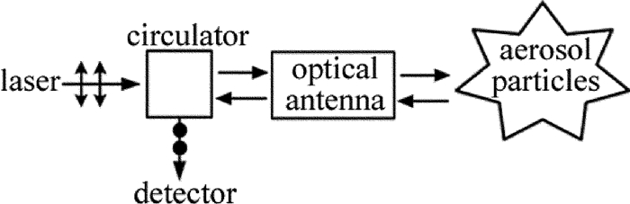
  • 许多光学系统正朝着可靠、小型、轻量化方向发展,这就需要设计折射式收发同轴的光学天线,以使光路稳定、结构紧凑。图 1为目前常用光学系统的光路图。激光器输出激光,经环行器准直后入射光学天线,通过调焦电机控制天线出射光束聚焦于不同的探测距离,激光与目标作用后,散射光再经天线和环行器被探测器接收。对于光学天线的设计,要求在系统探测范围内,光学质量接近衍射极限,并且在环境温度变化范围内,光学质量依旧接近衍射极限。根据需求,天线的设计指标为:波长λ=1.55μm,入瞳直径D1=3.8mm,视场角2ω=0.032°,物镜F数为2.2,总长l < 250mm,工作距离L=(50~3000)m,环境温度T=(-45~65)℃。

    Figure 1.  Diagram of atmospheric detection

2.   激光测风雷达折射式收发同轴光学天线设计
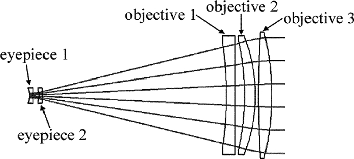
  • 考虑光学天线总长的限制,选择设计伽利略型光学天线,通过改变目镜组和物镜组间的间距实现光束在不同探测距离处的聚焦。同时,负目镜组对正物镜组进行像差补偿以满足光学质量。为避免湍流对相干探测的影响[16-18],光学天线口径应小于大气湍流相干长度,所以取天线口径D2=100mm。由此可计算出天线倍率Γ=26,物镜组焦距f2=220mm,目镜组焦距f1=-8.5mm。为了利用空气间隔校正系统像差,目镜组采用惠更斯目镜,同时因为天线口径的限制,物镜组采用3个分离透镜。初步设计的天线结构和参量分别如图 2表 1所示。目镜1、目镜2和物镜2、物镜3的材料选用成都光明器材有限公司的H-ZF10,物镜1选用熔融石英,孔径光阑设在物镜3的前表面,目镜2和物镜1的间距d为调焦变量。

    Figure 2.  Structure diagram of optical antenna

    No. radius/mm thickness/mm glass
    1 -15.50 3 H-ZF10
    2 35.33 6
    3 -13.24 3 H-ZF10
    4 -65.55 169
    5 -297.50 8 F_SILICA
    6 infinity 9
    7 -203.20 10 H-ZF10
    8 -129.60 3
    STO 852.30 12 H-ZF10
    10 -214.90

    Table 1.  Parameters of optical antenna

    光学天线的设计首先要满足常温使用要求。图 3为20℃时天线在不同工作距离处的像质情况,其中外圆为艾里斑。当L=50m时,d=170.21mm,系统焦距f=1.94m,所以艾里斑直径DA=2.44λf/D1=1931μm,天线各视场弥散斑的均方根直径分别为DRMS1=731.60μm, DRMS2=732.00μm,均小于艾里斑直径,同时l=224.2mm,满足设计要求。同理可得当L=3000m时,DA=37.82mm,DRMS1=11.67mm, DRMS2=11.71mm,l=223.3mm,同样满足设计要求。

    Figure 3.  Spot diagrams of the antenna in different distances at 20℃

3.   消热差分析
  • 光学天线的消热差设计采用光机被动消热差法,其原理是合理选择光学元件和机械结构材料,使得当环境温度变化时,光学离焦量和机械变化量相互补偿,从而保证不同探测距离处的光学像质要求。折射光学元件热差系数为[19]

    式中,α1为光学材料的热膨胀系数,n为光学材料的折射率,ΔnT为光学材料的折射率温度系数,Δn0T为空气的折射率温度系数。对于该光学天线,由于光谱唯一,所以忽略色差引起的离焦,光学离焦量为:

    式中,h1为第一近轴光线的高度,φ为天线总光焦度,hi为第i块透镜所分配光焦度的权重因子,βi为第i块透镜的热差系数,φi为第i块透镜的光焦度。

    温度变化时,机械材料的变化量为:

    式中,α2为机械材料的线性热膨胀系数,R为材料长度。所以,消热差设计需满足以下方程:

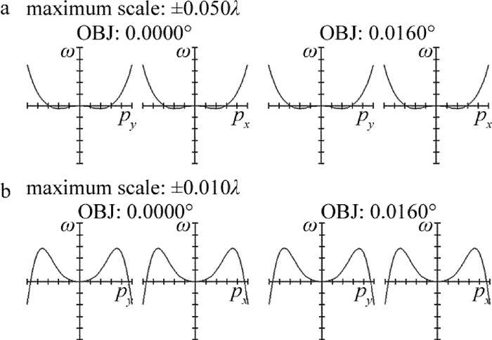
    根据(4)式,该光学天线镜筒材料选择铝合金,物镜1和物镜2间压圈材料选择钛合金,其它透镜间的压圈材料选择铝合金,利用ZEMAX软件进行消热差分析。图 4图 5分别为探测距离3000m时,天线在不同环境温度下的波像差图和能量包络图。图 4中,pxpy分别表示归一化入瞳的x分量和y分量。由图 4可知,当T=-45℃时,波像差(optical path difference,OPD)在全视场内的最大值为0.04λ; 当T=65℃时,OPD最大值为0.01λ,均小于0.25λ,满足衍射极限要求。因为光学系统受大气湍流空间相干长度的约束,若按强湍流折射率结构常数计算,目标处光学作用直径须小于120mm。从图 5可以看出,全视场内90%的能量集中在最大相干长度内,且能量分布集中,系统能量扩散仅受到衍射限制。同时,各视场的能量包络曲线近似重合,表明各温度场下各视场的弥散斑比较均匀,轴外像差较小,像质稳定。

    Figure 4.  OPD diagrams at 3000m

    Figure 5.  Encircled energy diagrams at 3000m

4.   实验与讨论
  • 实验系统包括1.55μm激光器、环行器、设计的光学天线、5m焦距透镜、上转换片、游标卡尺。天线调焦电机已提前完成标定,实验时可控制电机精确调焦到指定的工作距离。天线透镜在低温下因结霜而无法出光测量,所以需在天线做完高低温实验后立即进行测试。

    图 6连接实验系统,调节电机使天线聚焦于50m,然后停止调焦,记录光斑形状,如图 7所示。分别测量天线在20℃, -45℃和65℃时,工作距离50m处的光斑直径,结果如表 2所示。

    Figure 6.  Diagram of experiment system

    Figure 7.  Recording for spot diameter

    20℃ -45℃ 65℃
    simulation/mm 1.72 2.68 1.80
    measurement/mm 1.96 2.76 2.04

    Table 2.  Spot diameters under different temperatures (L=50m)

    通过观察20℃, -45℃, 65℃时,工作距离50m处的光斑形状,发现圆斑能量集中且分布均匀,像质均较好,验证了仿真结果。由表 2可知,仿真情况下,-45℃时光斑直径较20℃时增加了55%,65℃时较20℃时增加了5%,这是因为低温产生的系统离焦量大于高温产生的离焦量。实测情况下,-45℃和65℃时的光斑直径较20℃时分别增加了41%和4%,高低温对系统离焦影响与仿真结果一致。测量值大于仿真值的原因是调焦控制存在微米级误差,实测时会造成光学天线存在微量离焦。

    因为实验空间有限,并且对于设计的小口径天线,工作距离3000m近似无穷远,所以在天线出瞳后放置5m焦距透镜,用5m处的远场像质近似工作距离3000m处的像质。调节电机使天线聚焦于3000m,然后停止调焦,将5m焦距透镜置于天线出瞳后方,用光斑分析仪记录5m处光斑形状。分别测量天线在20℃, -45℃, 65℃时5m处的光斑直径,结果如表 3所示。

    20℃ -45℃ 65℃
    simulation/mm 0.25 0.33 0.252
    measurement/mm 0.32 0.44 0.324

    Table 3.  Spot diameters at different temperatures (L=3000m)

    观察各个温度下的光斑发现无切光现象,圆斑能量分布均匀,与仿真的能量包络图结果吻合。由表 3可知,远距离探测时,低温对系统离焦的影响很大,而高温的影响很小,实验与仿真结果相同。

5.   结论
  • 针对目前光学系统的发展趋势,设计了折射式收发同轴光学天线。基于设计指标,首先确定天线光学结构和相关光学参量,通过优化使其满足常温下不同工作距离处的像质要求。采用光机被动消热差法确定天线镜筒和隔圈的材料,利用ZEMAX进行热差分析,仿真结果表明, 在最大工作距离处,环境温度从-45℃变化到65℃时,天线像质依旧接近衍射极限。搭建实验平台观测不同工作距离不同环境温度下的光斑质量,验证了仿真结果。设计的折射式收发同轴光学天线体积小、可靠性高,在一定温度范围内性能稳定。

Reference (19)

Catalog

    /

    DownLoad:  Full-Size Img  PowerPoint
    Return
    Return