Advanced Search

ISSN1001-3806 CN51-1125/TN Map

Volume 41 Issue 5
Sep.  2017
Article Contents
Turn off MathJax

Citation:

Study on damage boundary extraction and shape reduction of laser cladding parts

  • Corresponding author: ZHANG Jianjie, zhang_jianjie@xju.edu.cn
  • Received Date: 2016-11-18
    Accepted Date: 2016-12-23
  • In order to extract the damage boundary of parts quickly and accurately, observe the process and results of parts damage and realize the shape reduction, and repair complex damaged parts by laser cladding remanufacturing, the defect types of the damaged parts were divided according to process characteristics of laser cladding, the damage boundary extraction and shape reduction methods of different types of defects were studied. The method of extracting boundary features of surface spots based on the curvature threshold and the normal vector threshold and the method of extracting boundary features of local deep damage based on 3-D comparison were proposed. The methods of shape reduction were presented, for the local deep damage parts by the traditional surface and for the superficial damage parts by the NURBS surface. And then, the experiments of laser cladding remanufacturing and restoration were carried out to verify the feasibility of the proposed method by path planning. The results show that the precision and efficiency of the extraction and restoration of the damaged area are improved and the cladding morphology waviness is smaller. The study provides the theoretical basis for the application of extraction and shape reduction of the damaged parts in laser cladding remanufacturing.
  • 加载中
  • [1]

    XU B S. Development status and prospect of green remanufacturing engineering[J] Engineering Sciences, 2011, 13(1):4-10(in Chinese).
    [2]

    JIANG F B, SHI Sh H, FU G Y. Numerical simulation of powder-gas flow field of inside-beam powder feeding nozzle with changing attitude[J].Laser Technology, 2015, 39(2):145-151(in Chinese).
    [3]

    GUO H M, WANG W J, LIU J H, et al. Effect of wheel cladding on wear and damage property of wheel/rail wear and under heavy-haul condition[J].Journal of Functional Materials, 2014, 45(9):9033-9042(in Chinese).
    [4]

    FU Y M, GAO Zh T, MA Y H, et al.Research on electromagnetic crack heat arrest and laser repaired in hot diemaetal[C]//International Conference on Advanced Technology of Design and Manufacture. New York, USA: IEEE, 2010: 338-341.
    [5]

    YANG C X, XU B, DENG Q L.The flexible fiber laser cladding processing research[J].Electromachining & Mould, 2012(s1):38-40(in Chinese).
    [6]

    DONG L, YANG X Ch, ZHANG H M, et al. Path generation for repairing damaged parts of free-form surfaces in laser remanufacturing[J]. Chinese Journal of Lasers, 2012, 39(7):703007(in Chinese). doi: 10.3788/CJL
    [7]

    LI J H, ZHANG D Q, YAO F P, et al. Study on 3-D remodeling of mold broken area based on reverse engineering[J]. Modular Machine Tool & Automatic Manufacturing Technique, 2014(9):33-38(in Chinese).
    [8]

    LIU L F, YANG X Ch. Path planning of laser remanufacturing robot based on reverse engineering[J]. Chinese Journal of Lasers, 2011, 38(7):703008(in Chinese). doi: 10.3788/CJL
    [9]

    YILMAZ O, NABILL G, GAO J. A repair and overhaul methodology for aeroenginecomponents[J]. Robotics and Computer-Integrated Manufacturing, 2010, 26(2):190-201. doi: 10.1016/j.rcim.2009.07.001
    [10]

    CHENG S Y, YU G X, ZHANG X W. Surface model reconstruction methodologies in reverse engineering system[J]. Computer Integrated Manufacturing Systems, 2008, 14(10):1934-1939(in Chinese).
    [11]

    CHENG Zh Q.Application of rapid surface modeling method[J]. Knowledge Economy, 2010(11):94(in Chinese).
    [12]

    ZHANG Sh P. Laser cladding repair for wearing teeth in excavator[J]. Hot Working Technology, 2014, 43(14):169-170(in Chinese).
    [13]

    LIU Sh L, ZHOU R R, ZHANG L Y. Feature line extraction from triangular mesh model[J]. Journal of Computer Aided Design & Computer Graphics, 2003, 15(4):444-448(in Chinese).
    [14]

    MO M L. Application of reverse engineering technology on automobile panel measuring & modeling[J]. Machine Tool & Hydraulics, 2008, 36(12):49-51.
    [15]

    TONG J W. Laser remanufacturing technology used in locomotive repair[J]. Railway Locomotive and Motor Car, 2014(10):21-27(in Chinese).
    [16]

    WANG W B, MA Z, LI A G, et al. Damaged area positioning for remanufacturing workpiece[J]. Bulletin of Science and Technology, 2010, 26(5):652-656(in Chinese).
  • 加载中
通讯作者: 陈斌, bchen63@163.com
  • 1. 

    沈阳化工大学材料科学与工程学院 沈阳 110142

  1. 本站搜索
  2. 百度学术搜索
  3. 万方数据库搜索
  4. CNKI搜索

Figures(14) / Tables(1)

Article views(3214) PDF downloads(201) Cited by()

Proportional views

Study on damage boundary extraction and shape reduction of laser cladding parts

    Corresponding author: ZHANG Jianjie, zhang_jianjie@xju.edu.cn
  • School of Mechanical Engineering, Xinjiang University, Urumqi 830047, China

Abstract: In order to extract the damage boundary of parts quickly and accurately, observe the process and results of parts damage and realize the shape reduction, and repair complex damaged parts by laser cladding remanufacturing, the defect types of the damaged parts were divided according to process characteristics of laser cladding, the damage boundary extraction and shape reduction methods of different types of defects were studied. The method of extracting boundary features of surface spots based on the curvature threshold and the normal vector threshold and the method of extracting boundary features of local deep damage based on 3-D comparison were proposed. The methods of shape reduction were presented, for the local deep damage parts by the traditional surface and for the superficial damage parts by the NURBS surface. And then, the experiments of laser cladding remanufacturing and restoration were carried out to verify the feasibility of the proposed method by path planning. The results show that the precision and efficiency of the extraction and restoration of the damaged area are improved and the cladding morphology waviness is smaller. The study provides the theoretical basis for the application of extraction and shape reduction of the damaged parts in laser cladding remanufacturing.

引言
  • 在我国,再制造经过萌芽和科研阶段,现如今已经进入全面发展阶段[1]。激光再制造的基础是激光熔覆技术。随着激光熔覆技术中熔覆层微观组织结构、凝固机制、力学性能、工艺参量、裂纹控制、光粉耦合、材料及系统设备等基础研究的不断深入,激光熔覆技术正在被广泛应用于破损零部件修复与强化[2-4]。六自由度机器人的引入给激光熔覆再制造系统柔性化提供了更优的方案,能够调整激光束的位姿,使激光束和粉末平行于曲面法矢方向而聚焦在曲面零件表面[5-6]。每一个零部件的破损情况都具有其独特唯一性且难以测量,特别是复杂曲面零件,为了不影响其没有破损的部位,提高再制造的针对性和修复效率,需要对破损零部件的破损区域进行边界提取和破损区域提取,提供零部件的破损区域的尺寸和定位信息,对零部件的破损情况进行全面评价,为后续的熔覆前机加工去除破损区域影响区或疲劳层等熔覆区域规划提供基础[7-8]。通过零件破损边界提取与形状还原来实现破损区域的检测定位、进行熔覆路径规划及形貌特征可视化,提高激光熔覆的柔性化和自动化程度,为破损零件获得高质量、高精度和高稳定性的熔覆涂层提供基础。

1.   破损边界提取及激光熔覆再制造修复系统的建立
  • 本系统采用天远3维扫描仪OKIO-V对破损零部件进行点云数据采集, 如图 1a所示。激光再制造系统包含激光制造系统、送粉系统、运动执行机构及工作台、软件控制系统以及其它辅助装置,本实验中采用的是美国IPG公司生产的4kW光纤激光器和德国KUKA机器人KR30HA,能实现柔性加工,系统布局如图 1b所示。

    Figure 1.  System equipment

2.   零件破损边界提取与形状还原在激光熔覆中的应用原理
  • 零件破损边界提取的原理分为两种。一种是通过点云数据采集获取破损零部件的表面点云数据,破损区域的边界往往是曲率极值和法矢突变点,通过对点云数据曲率和法矢的计算,提取曲率极值和法矢突变点作为零件破损区域的边界。另一种则是将破损零部件表面点云数据与标准CAD模型或标准零件点云数据进行3-D比较,通过求取标准数据模型与破损零部件表面点云数据的差集,得到零件破损区域的位置和形状特征参量[9]

    破损零件的形状还原包括传统曲面造型方法和快速曲面造型方法。传统曲面造型主要表现为由点-线-面的形状还原流程,根据点云数据构建特征曲线,然后利用放样、拉伸、旋转等曲面造型方法在特征曲线的基础上实现破损零件的形状还原[10]。快速曲面造型在点数数据的基础上进行网格化处理,建立多面体化表面。首先对点云数据进行预处理,在点处理阶段的基础上进行三角面片封装,得到由一系列三角面片组成的网格曲面;对三角面片进行填补空洞、修复相交、简化等处理,并对三角面片进行分块,得到拥有4条边界的一系列曲面片;对曲面片进行栅格细分,用NURBS曲面拟合每一个曲面片,并确保每一个曲面片的连续,从而完成破损零件的形状还原。

    零件破损边界的提取与形状还原包括点云数据采集、点云数据预处理、边界提取、形状还原及边界输出等流程,其流程图如图 2所示[11]

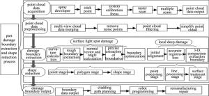
    Figure 2.  Process of damage boundary extraction and shape reduction of a part

3.   零件表面浅斑类损伤边界提取与形状还原
  • 表面浅斑损伤是指损伤深度较浅,一定程度单层熔覆可修复,包括局部磨损、浅裂纹、腐蚀等。因激光熔覆的再制造修复具有自动化和柔性化程度高、涂层材料性能可控,能形成与基体冶金结合、组织致密的涂层,广泛应用诸如磨损等表面浅斑损伤零件的再制造修复[12]

  • 在260mm×85mm×18mm的长方体零件上表面中心附近人为磨削一个形状不规则、深度不一的缺陷,如图 3a所示。进行多次多视角点云数据采集,得到原始点云数据,如图 3b所示。

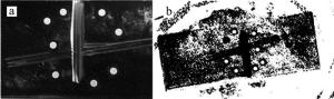
    Figure 3.  Test sample

    原始点云数据利用IGES文件格式,导入到Geomagic Studio中,然后进行多视点云拼合、去除体外孤点、去噪以及点云精简。计算点云数据所有点的平均曲率,然后取曲率阀值Hth=0.05对点云数据进行破损边界粗提取[13],提取出损伤边界,如图 4a所示。可以看出, 提取得到的粗边界包含了零件的轮廓边界,进行粗边界的优化处理,提取所需要区域的点云数据,如图 4b所示。计算出粗边界点云数据中所有顶点的法向量值,得到粗边界的顶点法矢分布图。进而得到所有顶点法矢夹角值,取法矢夹角阈值θth=60°[13],得到破损边界精提取的特征点集,如图 4c所示。从图中可以看出,破损边界精提取过程中将物体表面横切的几条细小凹槽也作为破损边界提取了,需要进行二次手动提取,提取后的零件破损边界包, 如图 4d所示。通过计算法向量夹角来提取破损边界特征点的方法简单、快捷,能够提取出破损区域的基本几何信息。

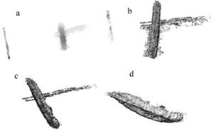
    Figure 4.  Damage boundary extraction

    通过提取零件损伤区域点云数据的坐标极限,得到破损区域的尺寸大小及定位信息,如图 5a所示。通过对实际破损件x方向进行尺寸测量,如图 5b所示。尺寸长度为70.80mm,与提取x方向的尺寸72.44mm,相对误差为2.3%,可见提取的尺寸精度较高。

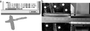
    Figure 5.  Size and location information of damage zone

    据表面浅斑损伤零件点云数据的特点,选择快速曲面造型方式中的NURBS曲面对表面浅斑损伤零件进行3维形状还原,同时采用软件Geomagic进行其形状还原。通过点阶段,多变形阶段,曲面阶段,最后利用IGES文件格式将还原模型导入到UG中,如图 6所示。

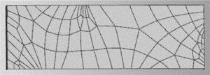
    Figure 6.  Reduction result

  • 利用分层切片原理截取每层熔覆边界特征点数据,得到点云集合,如图 7a所示。通过光顺和插补,得到边界特征点云,如图 7b所示。利用三次B样条曲线拟合分层切片边界,如图 7c所示,并分析拟合误差,如图 7d所示。从图中可以看出,通过三步优化处理后的分层点云具有较好的光顺性,拟合误差较小,且误差分布均匀,为后续的激光熔覆修复路径规划提供了良好的基础。

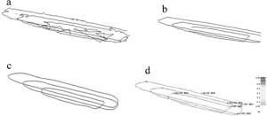
    Figure 7.  Point cloud output of damaged area

    根据边界拟合曲线,进行填充,规划熔覆路径,如图 8a所示。根据熔覆路径生成机器人熔覆控制程序,并进行缺陷再制造修复,修复后的效果如图 8b所示。

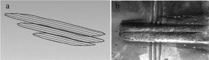
    Figure 8.  Repair of shallow surface defect

  • 破损零部件在车削、铣削或用手动砂轮机等机加工方式去除缺陷部位疲劳层后,针对机加工后的缺陷部位进行再制造修复,需要编写一定的机器人运动轨迹程序,而程序的编写就需要知道缺陷部位的位置和形状特征参量,而位置和形状特征参量就需要通过边界提取。

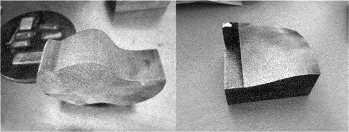
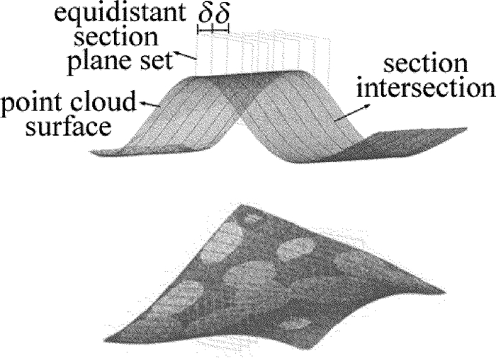
    采用3维扫描仪对曲面零件(S型和自由曲面如图 9所示)进行数据采集, 运用IMAGEWARE, GEOMAGIC QUALIFY和STUDIO软件对测量数据进行处理。因测量中不可避免地存在着测量误差, 尤其在曲率变化剧烈的部位, 因此, 需要对得到的点云数据进行处理, 筛选出异常数据[14]。处理好的曲面点云数据直接进行路径规划,并通过分析熔覆道搭接率来确定切平面间的距离, 取消了曲面点位置二次拟合的误差,利用NURBS曲面拟合并得出加工点的法向矢量,将熔覆扫描点的位置和矢量转化为机器人加工代码,结合机器人柔性加工特点,进行机器人连续变姿态熔覆加工,最后得到熔覆层表面形貌良好,厚度均匀,组织均匀致密且无明显裂纹和气孔。点云切片轨迹图如图 10所示,熔覆效果图如图 11所示。

    Figure 9.  Parts of the curved surface

    Figure 10.  The generated trajectory of cutting plane method

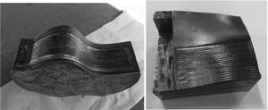
    Figure 11.  Cladding results

4.   零件局部深层类损伤边界提取与形状还原
  • 局部深层损伤(凹坑、断裂、穴蚀等)是齿轮、轴类等运动件常见的失效形式,其特点是零件整体保持完好,仅零件局部丧失使用性能[15]

  • 对120mm×120mm×30mm的长方体模具阴模进行加工时,在顶部错误铣削一个20mm×10mm×5mm的半椭球,导致模具失效。将其作为局部深层损伤区域零件,逆向得点云数据,进行预处理,得点云模型。然后对零件进行几何形貌分析,创建对齐参考特征,平面、直线和点,在点云中创建相似的特征,把创建的特征和点云进行群组。最后,将点云中的特征与世界坐标系中的参考特征对齐,如图 12a所示。在将点云数据对齐到世界坐标系下后,采用ICP算法[16]对点云数据与标准CAD模型进行再次配准。只需要对比中间椭球形区域进行精确配准,如图 12b所示。

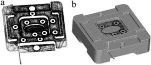
    Figure 12.  Accurate registration of parts

    通过3-D比较,对精确配准的点云模型和标准CAD模型进行偏差分析,得到3-D彩色偏差色谱图,如图 13a所示,图中椭圆形部分表示了局部深层损伤的3-D形貌和偏差大小。设定误差阀值为0.1mm,得到其局部深层损伤区域点云, 如图 13b所示。只在偏差较少的零件上表面和椭球接触区域存在部分噪声点。局部深层损伤区域点云信息如表 1所示。提取得到的损伤区域点云位置与损伤区域20mm×10mm×5mm半椭球形的损伤尺寸和定位吻合度极高。根据其破损区域特征,进行点云处理、曲线构造、曲面拟合,进而还原其形状, 如图 13c所示。

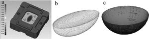
    Figure 13.  Results of theoretical analysis

    size/mm minimum/mm maximum/mm
    x 19.9376 49.9083 69.8459
    y 41.0000 16.5000 56.5000
    z 5.0340 -4.0000 1.0340

    Table 1.  Point cloud information of damage area

  • 根据前文中的边界输出原理提取每层熔覆边界特征点数据,得到分层切片点云。通过光顺和插补,得到边界特征点云。利用三次B样条曲线拟合分层切片边界,并分析拟合误差根据边界拟合曲线,进行填充,规划熔覆路径,如图 14a所示。根据熔覆路径生成机器人熔覆控制程序,并进行缺陷再制造修复,修复后的效果如图 14b所示。

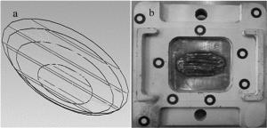
    Figure 14.  Local deep defect repair

5.   结论
  • 围绕复杂零件破损边界提取与形状还原在激光熔覆再制造中的应用展开,在提取零件破损边界的基础上,对破损零件进行形状还原。通过边界输出,最终生成熔覆控制程序,并进行了激光熔覆试验。

    (1) 针对复杂零件破损边界提取与形状还原在激光熔覆中的应用研究,在对破损零件损伤类别进行分类的基础上,提出了针对其类别破损边界提取和还原的方法,起高了破损零件破损边界提取和还原的精度和效率。

    (2) 根据不同的情况,进行激光熔覆修复路径规划,根据熔覆路径完成破损零件激光熔覆再制造修复。

    (3) 复杂零件的破损边界提取与还原是激光熔覆再制造修复的难题,对此本文中也只是对其进行了初步的研究。开发一套集成点云采集、破损零件边界提取、机器人编程和熔覆过程控制的系统,完成从破损零件的测量、边界提取、自适应激光熔覆、自适应机械加工以及自动化检测的系统化实现,提高熔覆再制造修复的自动化、柔性化程度,是下一步研究的方向。

Reference (16)

Catalog

    /

    DownLoad:  Full-Size Img  PowerPoint
    Return
    Return