Advanced Search

ISSN1001-3806 CN51-1125/TN Map

Volume 41 Issue 5
Sep.  2017
Article Contents
Turn off MathJax

Citation:

Research of rapid annealing of fiber Bragg gratings based on arc plasma

  • Corresponding author: ZHU Lianqing, zhulianqiang@sina.com
  • Received Date: 2016-11-14
    Accepted Date: 2017-01-06
  • In order to realize rapid annealing of fiber Bragg gratings, high temperature arc plasma heat treatment method was adopted. The related experiments were designed for verification. A fiber Bragg grating (FBG) with transmission spectrum depth of 23dB, central wavelength of 1552.09nm and 3dB bandwidth of 0.2784nm was scanned by arc plasma discharging. The results show that the transmission spectrum depth is reduced, the 3dB bandwidth is narrowed and the central wavelength shows blue shift. The variation trend of each parameter is slowed down with the increasing of the repetitive scanning times. Finally, the transmission spectrum depth is reduced by 13dB, the central wavelength is shifted blue by 0.84nm and the 3dB bandwidth is narrowed by 0.1013nm. After fiber grating is annealed in a high temperature furnace for 24h, the transmission spectrum depth, central wavelength and 3dB bandwidth remain the same. It is feasible to use arc plasma for the annealing of FBG with the advantages of short cycle and no damage of the coating layer.
  • 加载中
  • [1]

    WANG Y P, TANG J, YIN G L, et al. The fabrication method and sensing application of fiber grating[J]. Journal of Vibration, Measurment & Diagonosis, 2015, 35(5):809-819(in Chinese).
    [2]

    XU H F, YANG Zh Ch, LIU Sh Ch, et al. Application of fiber Bragg grating sensing technology in bridge piles[J]. Journal of China University of Metrology, 2012, 23(1):52-56(in Chinese).
    [3]

    COELHO L, VIEGAS D, SANTOS J L, et al. Optical sensor based on hybrid FBG/titanium dioxide coated LPFG for monitoring organic solvents in edible oils[J]. Talanta, 2016, 148(1):170-176.
    [4]

    WANG Ch, NI J Sh, WANG J Q, et al. All-fiber velocity sensors applicated in wind power generation and their fabrication process[J]. Laser Technology, 2012, 36(5):689-692(in Chinese).
    [5]

    LIU Sh Zh, ZHANG X, ZHENG X, et al. Application of distributed fiber Bragg grating sensor system in reactor coating layer[J]. Yunnan Electric Power, 2016, 44(1):87-89(in Chinese).
    [6]

    YU H Y, QIN X H, LIU Y D, et al. High-precision FBG sensor for human body temperature detection[J]. Optical Communication Technology, 2016, 40(4):33-35(in Chinese).
    [7]

    LIU Y Y, JIANG F X, HOU J P, et al. Research of inscription technique for multi-wavelength array fiber gratings in ribbon fiber[J]. Laser Technology, 2015, 39(4):484-487(in Chinese).
    [8]

    ZHONG X Y, WANG Y P, QU J L, et al. High-sensitivity strain sensor based on inflated long period fiber grating[J]. Optics Letters, 2014, 39(18):5463-5466. doi: 10.1364/OL.39.005463
    [9]

    WILLIAMS R J, KRÄMER R G, NOLTE S, et al. Femtosecond direct-writing of low-loss fiber Bragg gratings using a continuous core-scanning technique[J]. Optics Letters, 2013, 38(11):1918-1920. doi: 10.1364/OL.38.001918
    [10]

    GUO J C, YU Y S, XUE Y, et al. Compact long-period fiber gratings based on periodic microchannels[J]. IEEE Photonics Technology Letters, 2013, 25(2):111-114. doi: 10.1109/LPT.2012.2227701
    [11]

    NOORDEGRAAF D, SCOLARI L, LAGSAARD J, et al. Electrically and mechanically induced long period gratings in liquid crystal photonic bandgap fibers[J]. Optics Express, 2007, 15(13):7901-7912. doi: 10.1364/OE.15.007901
    [12]

    LEMAIRE P J, ATKINS R M, MIZRAHI V, et al. High pressure H2, loading as a techniquefor achieving ultrahigh UV photosensitivity and thermal sensitivity in GeO2, doped optical fibres[J]. Electronics Letters, 1993, 29(13):1191-1193. doi: 10.1049/el:19930796
    [13]

    NOGUCHI K, EUSUGI N, NEGISHI Y. Loss increase for optical fibers exposed to hydrogenatmosphere[J]. Journal of Lightwave Technology, 1985, 3(2):236-243. doi: 10.1109/JLT.1985.1074175
    [14]

    ATKINS R M, LEMAIRE P J, ERDOGAN T, et al. Mechanisms of enhanced UV photosensitivity via hydrogen loading in germanosilicate glasses[J]. Electronics Letters, 1993, 29(14):1234-1235. doi: 10.1049/el:19930825
    [15]

    LI J Zh, JIANG D Sh. Hydrogen loading and fiber Bragg grating[J]. Chinese Journal of Material Research, 2006, 20(5):517-522(in Chinese).
    [16]

    LI Y, ZHAO H, ZHU Ch, et al. Study on fiber gratings technology[J]. Laser and Infrared, 2006, 36(s1):749-754(in Chinese).
    [17]

    BISBEE D L. Splicing silica fibers with an electric arc[J]. Applied Optics, 1976, 15(3):796-798. doi: 10.1364/AO.15.000796
    [18]

    REGO G. Fibre optic devices produced by arc discharges[J]. Journal of Optics, 2010, 12(11):113002. doi: 10.1088/2040-8978/12/11/113002
    [19]

    ZHENG W N, ZHU L Q, ZHUNG W, et al. Influence of electrode discharge on fiber Bragg grating spectral characteristics[J]. Chinese Journal of Lasers, 2016, 43(7):0706003(in Chinese). doi: 10.3788/CJL
  • 加载中
通讯作者: 陈斌, bchen63@163.com
  • 1. 

    沈阳化工大学材料科学与工程学院 沈阳 110142

  1. 本站搜索
  2. 百度学术搜索
  3. 万方数据库搜索
  4. CNKI搜索

Figures(7) / Tables(1)

Article views(5751) PDF downloads(227) Cited by()

Proportional views

Research of rapid annealing of fiber Bragg gratings based on arc plasma

    Corresponding author: ZHU Lianqing, zhulianqiang@sina.com
  • 1. Beijing Engineering Research Center of Optoelectronic Information and Instruments, Beijing Information Science and Technology University, Beijing 100016, China
  • 2. School of Instrument Science and Opto-electronics Engineering, Hefei University of Technology, Hefei 230009, China

Abstract: In order to realize rapid annealing of fiber Bragg gratings, high temperature arc plasma heat treatment method was adopted. The related experiments were designed for verification. A fiber Bragg grating (FBG) with transmission spectrum depth of 23dB, central wavelength of 1552.09nm and 3dB bandwidth of 0.2784nm was scanned by arc plasma discharging. The results show that the transmission spectrum depth is reduced, the 3dB bandwidth is narrowed and the central wavelength shows blue shift. The variation trend of each parameter is slowed down with the increasing of the repetitive scanning times. Finally, the transmission spectrum depth is reduced by 13dB, the central wavelength is shifted blue by 0.84nm and the 3dB bandwidth is narrowed by 0.1013nm. After fiber grating is annealed in a high temperature furnace for 24h, the transmission spectrum depth, central wavelength and 3dB bandwidth remain the same. It is feasible to use arc plasma for the annealing of FBG with the advantages of short cycle and no damage of the coating layer.

引言
  • 光纤布喇格光栅(fiber Bragg grating, FBG)传感器对被感测信息采用波长编码的方式,具有体积小、抗干扰能力强、灵敏度高且易于组网、复用等优点[1]。目前已在民用工程、电力行业、航空航天、生物医学、环境监测等诸多领域发挥着日益重要的作用[2-6]

    自1978年第1根布喇格光纤光栅问世以来,光纤光栅的制备方法就受到了国内外学者的广泛关注。发展至今,已有紫外曝光制备法[7]、高频CO2激光脉冲写入法[8]、飞秒激光逐点写入法[9]、腐蚀刻槽制备法[10]、离子束注入法和机械微弯制备法[11]等刻写方法。而基于相位掩模板的紫外曝光刻写技术,因其简单灵活,对光源的相干性要求不高,便于光纤光栅的大规模生产,成为目前使用最为广泛的一种方法。该方法对于光纤的光敏性具有较强的依赖性,在刻写之前,需要对光纤进行增敏处理。相比于掺杂、火焰轻擦等增敏方法,载氢增敏技术具有简单易行且成本较低的优势,是目前提高光纤光敏性的主流方法[12]。当载氢光纤受到紫外光照射时,光纤中的氢分子与硅、锗原子发生化学反应,形成Ge—OH、Si—OH等化学键和缺陷中心[13-14],进而影响了纤芯的有效折射率。刻写完成后,光纤中未发生反应的氢分子和不稳定的Ge—OH键,会造成光栅光学特性的不稳定,从而导致光纤光栅的测量精度的下降[15]。因此,为了消除光纤中残余的氢分子和不稳定的Ge—OH键,需要对制备完成的光纤光栅进行退火处理。退火后,光纤光栅的透射谱深度、3dB带宽减小,中心波长蓝移[16]

    目前,对于光纤光栅的退火多使用高温炉。该退火方式缺点明显,退火时间较长,同时会破坏光纤表面涂覆层。因此,找到一种快速高效的退火方法对缩短光纤光栅制备周期具有重要的意义。电弧等离子体放电时,产生的温度场分布均匀,瞬时高温可达1800℃。目前已经广泛地应用于大芯径特殊光纤的熔接[17],特殊光纤微结构和新型光纤光栅的制备[18]。本课题组就电弧等离子体放电对光纤光栅光谱特性的影响进行了部分研究,发现电弧等离子体放电激励栅区,紫外激光刻写的FBG,光栅透射谱大幅下降,光谱蓝移0.38nm,3dB带宽减小; 飞秒激光刻写的FBG透射谱基本保持不变,光谱红移0.022nm; 特别地,当电极在栅区中心位置放电时,光栅反射率下降幅度达到最大8dB,表现出开关量特性[19]。其中,电弧等离子体放电对紫外激光刻写FBG光谱特性的影响类似于高温退火带来的影响。

    作者在此基础上,设计了相关实验,比较了电弧等离子体放电与高温退火对光栅光谱特性的影响,提出了一种基于高温电弧等离子的FBG快速退火的方法。据知,之前还少有采用该方法进行光栅退火的报道。实验发现,受电弧等离子体放电扫描后的光纤光栅,透射谱深度降低,中心波长蓝移,3dB带宽变窄,表现出类似于高温退火的现象。单次放电扫描的情况下,较高的电弧等离子体放电功率使得光栅透射谱深度在退火后保持不变,但中心波长较之于退火前仍发生了蓝移。该现象表明, 单次放电扫描并未实现FBG的完全退火。当以一定放电功率重复对栅区进行放电扫描时,随着扫描次数的增加,光纤光栅透射谱深度、3dB带宽趋于稳定,中心波长不再漂移,最终保持不变。将电弧等离子体处理后的光栅放入高温炉中进行退火。退火前后,光栅光谱保持不变。因此,以一定放电功率的电弧等离子体,对栅区进行多次放电扫描,可以实现紫外激光刻写FBG的快速退火。

1.   实验方案
  • 本文中采用的实验系统如图 1所示。从宽带光源出来的光波经环形器进入到光纤光栅中,一部分光波被光纤光栅反射回来,再经环形器进入光开关端口1。另一部分光波经光纤光栅后透射出来,进入光开关的端口2,光开关的端口3与光谱仪相连。通过来回切换光开关,可以实现在同一台光谱仪监测光纤光栅的反射谱和透射谱。光纤光栅的两端分别固定在电弧等离子体的光纤夹具上。其中,光谱仪型号为YOKOGAWA公司的AQ6370C,分辨率为0.02nm,扫描波长范围为600nm~1700nm。宽带光源为实验室自行研制的放大自发辐射光源,输出功率为13.3dBm,波段为C+L波段(1525nm~1610nm)。实验中采用Corning SMF-28e光纤,光纤有效折射率为1.4472。光栅刻写方法采用相位掩模板下准分子激光器紫外曝光的方法。为保证刻写效率,获得高质量的光纤光栅,刻写之前,将光纤放入80℃、12MPa载氢罐中进行载氢增敏处理,载氢时间72h。

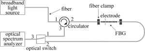
    Figure 1.  Experimental setup for FBG excited by arc plasma discharge

    电弧等离子体为美国3SAE公司生产的光纤涂层自动剥除机(3SAE FPUII)。放电扫描方式,从左至右,对整个栅区进行扫描。共进行两组实验,首先进行单次电弧等离子体放电扫描实验, 实验中采用不同放电功率,而扫描速率相同,为0.15mm/s。其次进行多次电弧等离子体放电扫描实验,实验中放电功率恒定55mW,扫描速率为0.15mm/s。

2.   实验结果与讨论
  • 规定以光纤光栅的最左端为起始点,电弧等离子体放电从左至右,对整个栅区进行扫描。实验中所需的6根光纤光栅,栅区长度均为10mm,将其分别标记为Ⅰ, Ⅱ, Ⅲ, Ⅳ, Ⅴ, Ⅵ。Ⅰ号光纤光栅为参考光栅。设置电弧等离子体放电功率为30mW, 40mW, 50mW, 60mW和70mW,以0.15mm/s的速率分别对Ⅱ~Ⅵ号光纤光栅的栅区进行放电扫描,扫描次数1次。扫描结束后,将Ⅰ~Ⅵ号光栅放入高温炉中进行退火。

    表 1是第1组实验中Ⅰ~Ⅵ号光纤光栅初始、放电扫描后、高温退火后的透射谱深度、中心波长、3dB带宽的值。从表中可以看到,参考光纤光栅经过高温退火后,透射谱深度由原来的14dB减小至11dB,Ⅱ号光纤光栅经电极放电扫描后的透射谱深度为12dB,退火后的透射谱深度为11dB。电弧等离子体放电扫描后,Ⅲ~Ⅵ号光栅透射谱深度均低于11dB,高温退火后透射谱深度保持不变,仍为11dB。经电弧等离子体放电扫描后,Ⅱ~Ⅵ号光纤光栅的中心波长蓝移。高温退火后,中心波长较之于退火前,仍发生了一定量的蓝移。

    label parameter original after discharging after annealing
    transmission/dB 14 11
    wavelength/nm 1552.49 1551.74
    3dB bandwidth/nm 0.2054 0.1818
    transmission/dB 14 12 11
    wavelength/nm 1552.84 1552.8 1552.07
    3dB bandwidth/nm 0.2029 0.1895 0.1774
    transmission/dB 14 10 10
    wavelength/nm 1552.33 1552.22 1551.54
    3dB bandwidth/nm 0.2097 0.1758 0.1763
    transmission/dB 14 8 8
    wavelength/nm 1552.89 1552.75 1552.08
    3dB bandwidth/nm 0.205 0.1574 0.159
    transmission/dB 14 6 8
    wavelength/nm 1552.61 1552.36 1552.2
    3dB bandwidth/nm 0.1942 0.1411 0.1405
    transmission/dB 14 4 4
    wavelength/nm 1552.58 1552.17 1552.14
    3dB bandwidth/nm 0.2012 0.1306 0.1301

    Table 1.  The grating parameters of Ⅰ-Ⅵ fiber gratings at different stages

    由上述可知,较之于退火前,经高功率放电扫描的FBG透射谱深度在退火后未发生变化,但中心波长有一定量的蓝移。该现象说明在单次放电扫描的情况下,单纯地提高电弧等离子体的放电功率,可以使FBG透射谱深度达到退火要求,但中心波长却无法满足。为了使经过电弧等离子体处理后的FBG在退火后,透射谱深度、中心波长均不发生改变,本文中进行了下一步实验,即在一定放电功率下,增加放电扫描次数。

  • 设置电弧等离子体放电功率为固定值55mW,以光纤光栅的最左端为起始点,电弧等离子体放电从左至右,以0.15mm/s的速率对整个栅区来回进行扫描,扫描次数记为N。光纤光栅初始透射谱深度14dB,中心波长1552.57nm,3dB带宽0.2057nm,栅区长度10mm。光纤光栅标记为14dB-FBG。

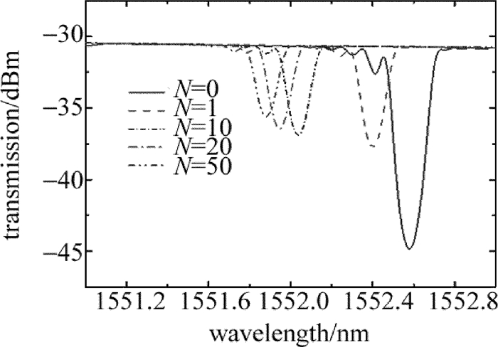
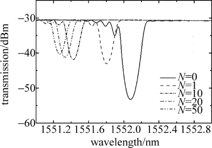
    图 2为第0次、第1次、第10次、第20次、第50次放电扫描结束后记录的14dB-FBG透射谱。由图中曲线可以看出,经过第1次电极扫描放电后,透射谱深度、3dB带宽明显下降,中心波长蓝移明显。

    Figure 2.  Relationship between transmission and wavelength of 14dB-FBG under different discharging times

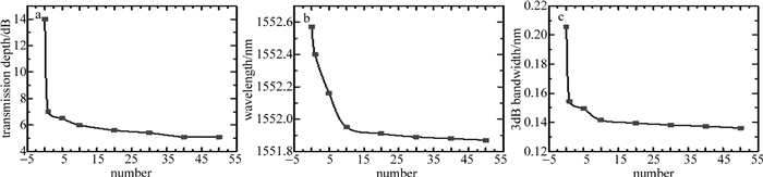
    光纤光栅透射谱深度、中心波长、3dB带宽随实验次数的变化趋势如图 3所示。随着放电次数的增多,FBG的透射谱深度、中心波长、3dB带宽变化逐渐平缓,最终保持不变,达到饱和。饱和状态下的光纤光栅透射谱深度为5dB,中心波长1551.90nm,3dB带宽0.1771nm。将饱和后的光纤光栅放入高温炉中进行退火处理。对比退火前与退火后的透射光谱和反射谱,如图 4所示。

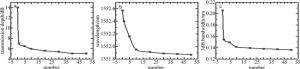
    Figure 3.  The changing trend of 14dB-FBG parameters under different discharging times

    Figure 4.  a—transmission of 14dB-FBG before and after annealing b—reflection of 14dB-FBG before and after annealing

    退火前后,光栅光谱特性一致。该现象表明以一定放电功率的电弧等离子体,多次扫描栅区可实现FBG的退火。然而,此时14dB-FBG的透射谱深度仅为5dB,影响了光纤光栅的反射率。为了提高电弧等离子体退火FBG的透射谱深度,采用初始透射谱深度更大的FBG进行实验。

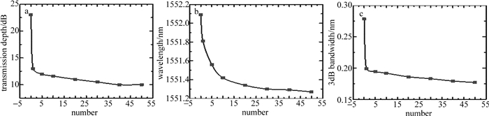
    电弧等离子体放电功率依然为固定值55mW,以同样的速度和方法对透射谱深度23dB,中心波长1552.09nm,3dB带宽0.2784nm,栅区长度10mm的光纤光栅栅区进行放电扫描。光纤光栅标记为23dB-FBG。随着实验次数的增加,其透射谱变化情况以及透射谱深度、中心波长、3dB带宽的变化趋势分别如图 5图 6所示。

    Figure 5.  Transmission spectrum of 23dB-FBG under different discharging times

    Figure 6.  The changing trend of 23dB-FBG parameters under different discharging tiems

    从图中可以看到,随着实验次数的增加,23dB-FBG透射谱深度、中心波长、3dB带宽变化逐渐平缓,最终保持不变,达到饱和。实验结果与14dB-FBG一致。饱和状态下的23dB-FBG透射谱深度10dB,中心波长1551.25nm,3dB带宽0.1771nm。透射谱深度大于14dB-FBG饱和状态下的5dB。对比退火前与退火后的透射谱与反射谱,如图 7所示,光栅光谱特性一致。说明经电弧等离子体多次放电扫描后,23dB-FBG实现了完全退火且此时仍旧具有较大的透射谱深度。

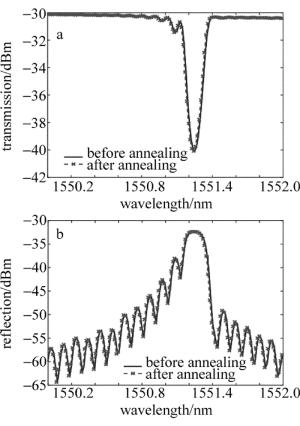
    Figure 7.  Comparison of 23dB-FBG

3.   结论
  • 将高温电弧等离子体用于FBG的退火处理, 研究了经电弧等离子体热处理后FBG的光谱特性。实验发现,单次放电扫描的情况下,较高的电弧等离子体放电功率使得光栅透射谱深度在退火后保持不变,但中心波长较之于退火前仍发生了蓝移。该现象表明,单次放电扫描并未实现FBG的完全退火。保证一定的放电功率,增加放电扫描次数,光纤光栅透射谱深度、3dB带宽趋于稳定,中心波长不再漂移,最终保持不变。现象与高温退火现象一致。将电弧等离子体处理后的光栅放入高温炉中进行退火,退火前后,光栅光谱特性不变,进一步说明了该方法实现了FBG的退火。本文中研究为紫外激光刻写FBG的退火提供了一种新方法,并且具有周期短、对光纤涂覆层无损伤的优点。文中主要研究了电弧等离子体放电功率和扫描次数对光纤光栅光谱特性的影响,至于电弧等离子体放电的其它参量给光纤光栅光谱特性带来的影响,仍需进一步的研究。

Reference (19)

Catalog

    /

    DownLoad:  Full-Size Img  PowerPoint
    Return
    Return