Advanced Search

ISSN1001-3806 CN51-1125/TN Map

Volume 41 Issue 2
Mar.  2017
Article Contents
Turn off MathJax

Citation:

A technique of quantitative imaging for phase object based on in-line interfermetry

  • Corresponding author: HUANG Zuohua, zuohuah@scnu.edu.cn
  • Received Date: 2016-01-04
    Accepted Date: 2016-03-14
  • In order to implement rapid quantitative phase measurement and imaging for transparent biological tissues, phase grating and other phase objects, based on the principle of in-line interferometry and phase contrast interferometry, an experimental system for fast quantitative measurement and imaging of phase objects was established. The principle of quantitative imaging was analyzed and the corresponding phase extraction and recovery procedures were designed. By shooting one or two phase contrast interferograms, the quantitative phase imagings for phase grating, water microdroplet and other phase objects with small phase variation were realized by the proposed method. A corresponding partition differential phase unwrapping algorithm was designed and the quantitative phase measurement and imaging of micro lens with phase value over π was achieved. The results show that the relationship between phase distribution of the obtained holographic phase grating measured by the system and phase amplitude variation of weak ultrasonic standing wave grating under different ultrasonic driving voltages is basically consistent with the results obtained from other methods. The experimental measurement of micro lens is compared with the theoretical value, and the absolute error is about 0.03μm. This system has certain feasibility, adaptability and potential applications on fast measurement and imaging of transparent phase objects such as biological cells and tissues.
  • 加载中
  • [1]

    RAJSHEKHAR G, BHADURI B, EDWARDS C, et al. Nanoscale topography and spatial light modulator characterization using wide-field quantitative phase imaging[J]. Optics Express, 2014, 22(3):3432-3438. doi: 10.1364/OE.22.003432
    [2]

    EDWARDS C, MCEOWN S J, ZHOU J, et al. In situ measurements of the axial expansion of palladium microdisks during hydrogen exposure using diffraction phase microscopy[J]. Optical Materials Express, 2014, 4(12):2559-2564. doi: 10.1364/OME.4.002559
    [3]

    LUE N, CHOI W, BADIZADEGAN K, et al. Confocal diffraction phase microscopy of live cells[J]. Optics Letters, 2008, 33(18):2074-2076. doi: 10.1364/OL.33.002074
    [4]

    LARIN K V, ELEDRISI M S, MOTAMEDI M, et al. Noninvasive blood glucose monitoring with optical coherence tomography:a pilot study in human subjects[J]. Diabetes Care, 2002, 25(12):2263-2267. doi: 10.2337/diacare.25.12.2263
    [5]

    HUANG Z H, CHEN F C. A new method of scanning image for phase objects[J]. Proceedings of the SPIE, 2006, 6150:1-5.
    [6]

    FERCHER A F, DREXLER W, HITZENBERGER C K, et al. Optical coherence tomography-principles and applications[J]. Reports on Progress in Physics, 2003, 66(2):239-303. doi: 10.1088/0034-4885/66/2/204
    [7]

    FLUERARU C, SHERIF S. Optical coherence tomography technology and applications[J]. Medical Physics, 2009, 36(10):147-148.
    [8]

    MARQUET P, RAPPAZ B, MAGISTRETTI P J, et al. Digital holographic microscopy:a noninvasive contrast imaging technique allowing quantitative visualization of living cells with subwavelength axial accuracy[J]. Optics Letters, 2005, 30(5):468-470. doi: 10.1364/OL.30.000468
    [9]

    MONEMAHGHDOUST Z, MONTFORT F, CUCHE E, et al. Full field vertical scanning in short coherence digital holographic microscope[J]. Optics Express, 2013, 21(10):12643-12650. doi: 10.1364/OE.21.012643
    [10]

    IKEDA T, POPESCU G, DASARI R R, et al. Hilbert phase microscopy for investigating fast dynamics in transparent systems[J]. Optics Letters, 2005, 30(9):1165-1167.
    [11]

    POPESCU G, IKEDA T, BEST C A, et al. Erythrocyte structure and dynamics quantified by Hilbert phase microscopy[J]. Journal of Biomedical Optics, 2005, 10(6):1720-1722.
    [12]

    XUE L, LAI J, WANG S, et al. Single-shot slightly-off-axis interferometry based Hilbert phase microscopy of red blood cells[J]. Biomedical Optics Express, 2011, 2(4):987-995. doi: 10.1364/BOE.2.000987
    [13]

    POPESCU G, IKEDA T, DASARI R R, et al. Diffraction phase microscopy for quantifying cell structure and dynamics[J]. Optics Letters, 2006, 31(6):775-777. doi: 10.1364/OL.31.000775
    [14]

    PHAM H, BHADURI B, DING H, et al. Spectroscopic diffraction phase microscopy[J]. Optics Letters, 2012, 37(16):3438-3440. doi: 10.1364/OL.37.003438
    [15]

    GAO P, YAO B L, HARDER I, et al. Phase-shifting Zernike phase contrast microscopy for quantitative phase measurement[J]. Optics Letters, 2011, 36(21):4305-4307. doi: 10.1364/OL.36.004305
    [16]

    LUE N, CHOI W, POPESCU G, et al. Quantitative phase imaging of live cells using fast Fourier phase microscopy[J]. Applied Optics, 2007, 46(10):1836-1842. doi: 10.1364/AO.46.001836
    [17]

    FVRHAPTER S, JESACHER A, BERNET S, et al. Spiral phase contrast imaging in microscopy[J]. Optics Express, 2005, 13(3):689-694. doi: 10.1364/OPEX.13.000689
    [18]

    WANG Z, MILLET L, MIR M, et al. Spatial light interference microscopy (SLIM)[J]. Optics Express, 2011, 19(2):1016-1026. doi: 10.1364/OE.19.001016
    [19]

    DING H, POPESCU G. Instantaneous spatial light interference microscopy[J]. Optics Express, 2010, 18(2):1569-1575. doi: 10.1364/OE.18.001569
    [20]

    GAO P, HARDER I, NERCISSIAN V, et al. Phase-shifting point-diffraction interferometry with common-path and in-line configuration for microscopy[J]. Optics Letters, 2010, 35(5):712-714. doi: 10.1364/OL.35.000712
    [21]

    GAO P, YAO B L, HARDER I, et al. Parallel two-step phase-shifting digital holograph microscopy based on a grating pair[J]. Journal of the Optical Society of America, 2011, A28(3):434-440.
    [22]

    GAO P, YAO B L, MIN J W, et al. Parallel two-step phase-shifting point-diffraction interferometry for microscopy based on a pair of cube beamsplitters[J]. Optics Express, 2011, 19(3):1930-1935. doi: 10.1364/OE.19.001930
    [23]

    BORN M, WOLF E. Principles of optics:electromagnetic theory of propagation, interference and diffraction of light[M]. 3rd ed. Cambridge, UK:Cambridge University Press, 1999:472-476.
    [24]

    BELEGGIA M. A formula for the image intensity of phase objects in Zernike mode[J]. Ultramicroscopy, 2008, 108(9):953-958. doi: 10.1016/j.ultramic.2008.03.003
    [25]

    YANG H, HUANG Z H, LIU Y. Analysis of phase-contrast method with background light[J]. Laser Technology, 2011, 35(5):696-698(in Chinese).
    [26]

    HUANG M N, HUANG Z H, CAI W X, et al. Manufacturing method of a phase plate and its application in phase-contrast experiments[J]. Laser Technology, 2010, 34(1):81-84(in Chinese).
    [27]

    PAN M Y, ZENH Y Zh, HUANG Z H. Quantitative measurement of phase variation amplitude of ultrasonic diffraction grating based on diffraction spectral analysis[J]. Review of Scientific Instruments, 2014, 85(9):093112. doi: 10.1063/1.4895649
    [28]

    GAO P, YAO B L, HAN J, et al. Phase reconstruction from three interferograms based on integral of phase gradient[J]. Journal of Modern Optics, 2008, 55(14):2233-2242. doi: 10.1080/09500340802082392
    [29]

    XIA H T, GUO R X, FAN Z B, et al. Non-invasive mechanical measurement for transparent objects by digital holographic interferometry based on iterative least-squares phase unwrapping[J]. Experimental Mechanics, 2012, 52(4):439-445. doi: 10.1007/s11340-011-9516-x
  • 加载中
通讯作者: 陈斌, bchen63@163.com
  • 1. 

    沈阳化工大学材料科学与工程学院 沈阳 110142

  1. 本站搜索
  2. 百度学术搜索
  3. 万方数据库搜索
  4. CNKI搜索

Figures(6)

Article views(6868) PDF downloads(328) Cited by()

Proportional views

A technique of quantitative imaging for phase object based on in-line interfermetry

    Corresponding author: HUANG Zuohua, zuohuah@scnu.edu.cn
  • Laboratory of Quantum Engineering and Quantum Materials, School of Physics and Tele-communication Engineering, South China Normal University, Guangzhou 510006, China

Abstract: In order to implement rapid quantitative phase measurement and imaging for transparent biological tissues, phase grating and other phase objects, based on the principle of in-line interferometry and phase contrast interferometry, an experimental system for fast quantitative measurement and imaging of phase objects was established. The principle of quantitative imaging was analyzed and the corresponding phase extraction and recovery procedures were designed. By shooting one or two phase contrast interferograms, the quantitative phase imagings for phase grating, water microdroplet and other phase objects with small phase variation were realized by the proposed method. A corresponding partition differential phase unwrapping algorithm was designed and the quantitative phase measurement and imaging of micro lens with phase value over π was achieved. The results show that the relationship between phase distribution of the obtained holographic phase grating measured by the system and phase amplitude variation of weak ultrasonic standing wave grating under different ultrasonic driving voltages is basically consistent with the results obtained from other methods. The experimental measurement of micro lens is compared with the theoretical value, and the absolute error is about 0.03μm. This system has certain feasibility, adaptability and potential applications on fast measurement and imaging of transparent phase objects such as biological cells and tissues.

引言
  • 近十几年来, 光学成像技术在微加工制造、材料科学和物态分析等领域, 尤其是生物医学领域得到了广泛应用[1-4]。其中, 透明生物样品的定量相位成像(quantitative phase imaging, QPI)是当前生物光学成像的研究热点之一。单点定量相位成像技术[5-7]可提供样品给定点的定量光相移信息, 通过扫描实现对样品的成像。这类成像技术测量速度较慢、测量范围较小、应用范围具有一定局限性。全场定量相位成像技术可同时提供样品上大量点的光相移信息, 有利于研究生物系统的时间和空间行为。其中离轴定量相位成像技术, 如数字全息显微术[8-9]、希尔伯特相位显微术[10-12]和衍射相位显微术[13-14], 可从单幅载频干涉图中获得包括相位信息在内的被测样品信息, 可快速实现物体的成像及其动态过程的测量, 但是其实验系统和相位恢复计算过程较为复杂。此外, 由于其采用离轴结构, 不能充分利用CCD的空间分辨率。同轴定量相位成像技术[15]能够充分利用CCD的空间分辨率, 如快速傅里叶相位显微术[16]、螺旋相位显微术[17]以及空间光干涉显微术[18-19]等。这类成像技术多数基于相移干涉技术, 一般需要连续获取3幅以上图像, 因此较难实现实时测量。GAO等人[20-22]提出了同步相移干涉显微术解决了不能同时采集相移干涉图的问题, 但是还是需要获取两幅干涉图像以及控制参考光和物光的强度比值才能进行样品的相位重建。

    本文中基于共轴干涉原理, 构建了一套相位物体定量相位快速测量与成像实验系统及方法。该系统只需拍摄单幅或两幅相衬干涉图像, 即可实现对小相位变化物体的定量成像与测量。实验中得到全息相位光栅、水滴和玉米根尖细胞的相位分布图, 以及不同超声驱动电压下驻波超声光栅的平均相位振幅与驱动电压的关系。为拓展其相位测量范围, 针对某些已知其相位变化趋势的相位物体, 设计了相应的能使恢复的相位值超过π的分区差分相位解包裹算法, 并通过对微透镜阵列进行相位测量来验证该解包裹算法的可行性。本实验系统与方法在透明生物细胞、组织的定量测量及成像方面有潜在的实际应用意义。

1.   共轴干涉定量相位成像原理
  • 假设单色平面光波正入射于一纯相位物体上, 其复振幅分布可表示为:

    式中, A为入射光的振幅, φ(x, y)为物体的相位分布。

    若忽略相干光学系统有限孔径的影响, 根据相衬干涉原理[23-25], 相衬像光强分布可表示为:

    式中, tφd分别为频谱面上相板的振幅透过率和相移量。(2)式也可转化为:

    式中, $B = \sqrt {1 + {t^2} - 2t\cos {\varphi _{\rm{d}}}} , \beta = {\rm{arctan}}\frac{{t\sin {\varphi _{\rm{d}}}}}{{t\cos {\varphi _{\rm{d}}} - 1}}$。其中, B表示干涉条纹振幅, β表示条纹相位, 其大小仅与所采用的相板参量tφd有关。由此可见, 相衬像光强I(x, y)与相位物体的相位φ(x, y)的成余弦关系。

    由(3)式可知, 相衬像光强分布实质上是两束相干光的干涉结果。

    若不移动相板, 直接移开样品或让样品中不含物体信息的区域通过光场, 此时, 像面背景光强度可表示为:

    根据I(x, y)和I0可计算得到被测样品的相位主值分布为:

    由(5)式可以唯一确定0~π范围内的相位值, 因此, 当被测物体相位变化较小时, 即其相位分布变化范围在π以内时, φ(x, y)的值能直接反映物体的真实相位分布。由于很多透明生物细胞与组织样品的相位变化范围小于π, 利用上述反余弦关系, 通过拍摄两幅相衬图像, 便能够得到被测相位物体的相位分布。如纯相位物体相位变化部分只占据整幅图像很小一部分时, 可将相衬图像中除去物体以外的区域看作背景光区域, 也可得到I0。因此只需采集单幅相衬图就可求解相位值, 有利于实时监测生物细胞或组织的生长引起的相位变化分布。

2.   实验及结果分析
  • 为了验证上述相位测量方法的可行性, 搭建了如图 1所示的实验装置。光源采用半导体二极管激光器(波长为635nm, 功率为5mW); 偏振片P用于调节实验时的入射光强度, 使得CCD面阵探测器工作在正常线性感光范围内; 激光束通过扩束镜、针孔滤波器和准直透镜L1(焦距为180mm)后形成平面光波照明样品; 可变光阑(直径可调范围为3mm~22mm)用于控制光场大小以及限制部分杂散光干扰; 在成像透镜L2(焦距为180mm)的后焦面上获得样品的频谱; 该平面上放置能够对零级分量进行相位调制的相板。该相板由全息干版制作而成, 并采用双点源干涉测量与扫描成像系统检测其相移量[26]; 使用CCD数字摄像机(型号Guppy PRO F-125B, 像元尺寸为3.75μm)对相衬干涉图像图样进行采集。

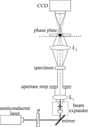
    Figure 1.  Experimental setup

  • 实验中选择了对全息相位光栅、驻波超声光栅以及玉米根尖细胞等小相位变化的相位物体作为样品进行了定量成像实验, 并在MATLAB平台设计了相关的数据处理程序, 重建了样品的相位分布。实验中所选相板的光强透过率为0.20, 相移量为0.60π, 相板直径约为0.30mm。

    全息相位光栅定量成像结果如图 2所示。图 2a为相位光栅的相衬光强分布图; 图 2b为反演计算得到的3维相位定量重建图; 图 2c为全息相位光栅相位截面分布图, 可见全息相位光栅周期为200μm左右, 相位起伏程度并不均匀, 相位变化范围为0rad~1.30rad左右, 与双点源干涉扫描定量相位测量方法[26]得到的结果(见图 2d)基本一致。重建相位误差可能与光栅分布不均匀及两种方法对该相位光栅的成像区域有一定差异有关。

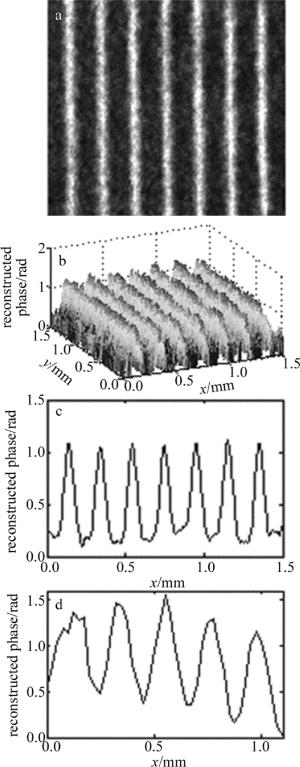
    Figure 2.  Quantitative phase imaging of holographic phase grating

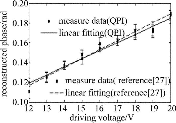
    为了进一步验证该方法的可靠性及实用性, 将被测样品换成驻波超声相位光栅进行实验。通过改变超声驱动电压, 得到不同驱动电压下驻波超声相位光栅的相衬干涉图像, 从而可以求得相应电压下的相位分布, 再求得其平均相位振幅大小。图 3为本实验中驻波超声光栅相位振幅与超声驱动电压的关系曲线。由图 3可知, 其平均相位振幅与驱动电压基本成线性关系, 这与采用参考文献[27]中所述方法的测量结果基本一致。

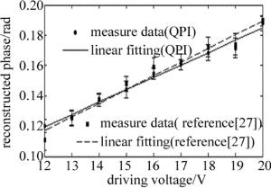
    Figure 3.  Relation between the average value of phase amplitude of standing ultrasonic grating and ultrasonic driving voltage

    在样品后添加显微物镜(倍率为10×), 可得到玉米根尖细胞的定量相位成像结果, 见图 4。可见, 玉米根尖细胞轮廓明显, 相位结构分布清晰, 且相位值不超过π。证明了该系统能用于生物样品的定量显微成像与测量, 具有一定实用性。

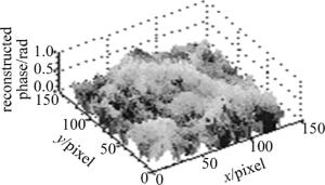
    Figure 4.  Quantitative phase imaging of corn root tip cells (10×)

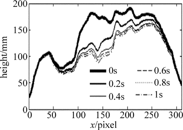
    此外, 还采用了该实验系统实时记录了垂直放置载玻片表面微小水滴在重力影响下的蒸发过程, 得到蒸发过程中各时刻的相位分布及厚度分布。图 5为该水滴在接近蒸发结束的某一秒内的厚度分布变化剖面图(水折射率取为1.33)。

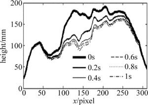
    Figure 5.  Height distribution and variation of a water microdroplet at different times

  • 若样品相位变化范围超过π, 则需要对相衬干涉图像进行相位解包裹运算才可得到正确的物体相位信息。针对部分相位值连续且单调变化的相位物体, 可以采用下述的适用于余弦式包裹相位的分区差分相位解包裹算法。

    根据余弦函数的偶函数特征可知, 相位包裹值φunwrap(x, y)在0到π再到0的范围内反复变化, 形成周期为2π的相位包裹膜。以相位真实值的最小值位置开始, 沿相位值单调递增方向, 假设第k个包裹周期的包裹相位值为φk, unwrap(x, y), 实际相位值为φk(x, y), 则本文中采用的相位恢复处理思想如下。

    (1) 当φk, unwrap(x, y)在0~π范围内单调递增时:

    (2) 当φk, unwrap(x, y)在π~0范围内单调递减时:

    该算法对于判定φk, unwrap(x, y)范围所使用的方法是:首先沿相位值递增方向, 将所提取到的包裹相位图像进行适当分区, 再对xy两个方向上的相邻像元值进行差分运算, 若符合一定的正负规律即可知道φk, unwrap(x, y)的范围, 从而根据(6)式和(7)式进行相应的相位恢复运算, 得到相位波面被限制在2π范围内的相位图, 再应用基于反正切函数的相关解包裹算法, 便可快速恢复出样品相位真实值[28-29], 实现对大相位物体的定量相位重构成像。

    为了验证上述解包裹算法的可行性, 选择了微透镜阵列作为样品进行实验测量与分析。图 5为采用本方法对微透镜阵列进行测量所得的实验结果, 单个微透镜尺寸为0.25mm×0.25mm, 焦距为10mm。图 6a图 6b分别为微透镜的相衬干涉图及相位再现3维图。微透镜的相位最大值为16.77rad, 位于微透镜中心。根据基底折射率和所测相位值可以得到截面处厚度约为3.49μm, 与厂家给定的参量计算得到的标准值(3.52μm)相比, 绝对误差约为0.03μm。

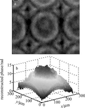
    Figure 6.  Imaging results of microlens array

3.   结论
  • 构建了一套基于共轴相衬干涉的定量相位测量与成像系统。对于相位变化范围不超过π的相位物体可以直接从相衬图中快速反演获得其定量相位分布; 对于相位变化范围超过π的物体, 可结合分区相位解包裹算法获得其真实的相位分布。对小相位变化物体定量相位测量及成像结果表明:共轴相衬干涉的定量相位测量与成像系统及方法具有成像过程简单、快速及可靠性高等特点。若对该系统及方法进一步地完善, 将期望在传统相衬显微成像系统中得到实际应用, 提高相衬显微镜的定量相位测量与成像功能。

Reference (29)

Catalog

    /

    DownLoad:  Full-Size Img  PowerPoint
    Return
    Return