Advanced Search

ISSN1001-3806 CN51-1125/TN Map

Volume 41 Issue 2
Mar.  2017
Article Contents
Turn off MathJax

Citation:

Influence of circulator parameters of coherent wind lidar on distance measurement

  • Received Date: 2016-03-22
    Accepted Date: 2016-07-18
  • In order to improve the capability of wind lidar, based on mathematics modeling method and circulator principle, the transmitted beam quality of circulator was analyzed. The influence of divergence angle on the peak intensity at target distance was discussed. The definition of coupling efficiency of circulator was proposed. And the influence of misalignment between transmitting and receiving axis on detection range was researched. Experimental platform was built to obtain spot parameters in the far field. The simulation results were verified. The results show that, the relative peak intensity at the same distance decreases with the increasing of divergence angle of transmitted beam. The detection range of lidar is mainly affected by misalignment, and misalignment of mrad would make detection range decrease by 89.7%. Therefore, the collimation ratio of optical antenna should be increased reasonably and the structure precision for adjusting misalignment should be better than 0.1mrad level.
  • 加载中
  • [1]

    KAMEYAMA S, ANDO T, ASAKA K, et al. Compact all-fiber pulse coherent Doppler lidar system for wind sensing[J]. Applied Optics, 2007, 46(11):1953-1962. doi: 10.1364/AO.46.001953
    [2]

    MICHAEL J K, ROD G F. Parameter trade studies for coherent lidar measurements of wind from space[J]. Proceedings of the SPIE, 2007, 6681:668109. doi: 10.1117/12.737429
    [3]

    CHIRSTER J K, FREDRIK A A O, DIETMAR L, et al. All-fiber multifunction continuous-wave coherent laser radar at 1.55μm for range, speed, vibration, and wind measurements[J]. Applied Optics, 2000, 39(21):003716. doi: 10.1364/AO.39.003716
    [4]

    FENG L T, GUO H Q, CHEN Y, et al. Experiment of all fiber Doppler lidar at 1.55μm[J]. Infrared and Laser Engineering, 2011, 40(5):844-847(in Chinese).
    [5]

    KOTANI T, ENYA K, NAKAGAWA T, et al. Development of a wave front correction system for the SPICA coronagraph instrument, space telescopes and instrumentation[J]. Optical, Infrared, and Millimeter Wave, 2010, 31(3):7731-7737.
    [6]

    WANG G Ch, DOU X K, XIA H Y, et al. Performance of a Raleigh Doppler lidar for middle atmosphere wind measurement[J]. Infrared and Laser Engineering, 2012, 41(9):2351-2357.
    [7]

    TANG L, SHU Zh F, DONG J H, et al. Mobile Rayleigh Doppler wind lidar based on double-edge technique[J]. Chinese Optics Letters, 2010, 8(1):8-15.
    [8]

    REDDING B, CHOMA M A, CAO H. Speckle-free laser imaging using random laser illumination[J]. Nat Photonics, 2012, 6(6):355-359. doi: 10.1038/nphoton.2012.90
    [9]

    JENNESS J R, LYSAK D B, PHILBRICK R, et al. Design of a lidar receiver with fiber optic output[J]. Applied Optics, 1997, 36(18):4278-4284. doi: 10.1364/AO.36.004278
    [10]

    RAMOS I L, SCOTT V S, SCHMIDT S, et al. Optical system design and integration of the mercury laser altimeter[J]. Applied Optics, 2005, 44(9):1748-1760. doi: 10.1364/AO.44.001748
    [11]

    ZHAO E G, CHEN G H. Development of 1053nm fiber optic circulator[J]. Optical Fiber & Electric Cable, 2008, 4(1):26-28(in Chinese).
    [12]

    ZHANG Y, ZHAO Y, TANG M, et al. Analysis of the alignment errors on performance measurement of optical scanner of laser radar[J]. Infrared and Laser Engineering, 2006, 35(2):139-142(in Chinese).
    [13]

    ZENG X, WU B, SHI X D, et al. Study on airborne laser cloud particle imaging probe and its calibration[J]. Laser Technology, 2015, 39(6):798-801(in Chinese).
    [14]

    BU L B, SHAN K L, HUANG X Y. Studies on probe of cloud droplet[J]. Chinese Journal of Lasers, 2009, 36(1):216-218(in Chinese). doi: 10.3788/JCL
  • 加载中
通讯作者: 陈斌, bchen63@163.com
  • 1. 

    沈阳化工大学材料科学与工程学院 沈阳 110142

  1. 本站搜索
  2. 百度学术搜索
  3. 万方数据库搜索
  4. CNKI搜索

Figures(7) / Tables(2)

Article views(3201) PDF downloads(258) Cited by()

Proportional views

Influence of circulator parameters of coherent wind lidar on distance measurement

  • Southwest Institute of Technology and Physics, Chengdu 610041, China

Abstract: In order to improve the capability of wind lidar, based on mathematics modeling method and circulator principle, the transmitted beam quality of circulator was analyzed. The influence of divergence angle on the peak intensity at target distance was discussed. The definition of coupling efficiency of circulator was proposed. And the influence of misalignment between transmitting and receiving axis on detection range was researched. Experimental platform was built to obtain spot parameters in the far field. The simulation results were verified. The results show that, the relative peak intensity at the same distance decreases with the increasing of divergence angle of transmitted beam. The detection range of lidar is mainly affected by misalignment, and misalignment of mrad would make detection range decrease by 89.7%. Therefore, the collimation ratio of optical antenna should be increased reasonably and the structure precision for adjusting misalignment should be better than 0.1mrad level.

引言
  • 相干激光测风雷达作为大气风场探测装备,正向着小型化、轻量化发展[1-4],这就需要采用收发合一的光学系统。环行器是激光收发分离的枢纽,出射光束质量严重影响回波信号强度和雷达探测距离[5-7],所以有必要对激光测风雷达环行器的光束质量进行分析。

    近年来,国内外许多学者做了相关研究。REDDING等人通过改进激光器设计减小了远场散斑对激光雷达成像的影响[8],但成像并不是测风雷达的核心。JENNESS等人针对收发分离的激光雷达系统,研究了光纤位置对回波信号的接收情况[9],但没有考虑收发合一系统。RAMOS等人利用平行光管测量了光学系统发射轴和接收轴的配准度[10],但系统没有包含环行器。ZHAO等人基于三端口环行器分析了光束发散角对耦合效果的影响[11],但忽略了结构加工精度限制所造成的发射和接收端口光轴不同轴问题。ZHANG等人从理论上讨论了对准误差对光学系统性能的影响[12],但缺乏实验验证。

    本文中从激光测风雷达环行器的工作原理出发,首先分析了在雷达探测范围确定情况下,环行器出射光束发散半角对峰值光强的影响,然后讨论了环行器发射和接收光轴之间偏轴度对光束接收效率的影响,最后通过实验对仿真结果进行验证分析并得出结论,为光学器件最优化配置和结构参量合理化设计提供理论依据。

1.   环行器原理
  • 环行器工作原理如图 1所示。脉冲激光器输出光纤发射的p偏振光经光纤准直器准直为平行光,然后经过偏振分束棱镜和λ/4波片变为圆偏振光,再经光学天线传输到大气中,大气散射回波光经波片变为s偏振光,由于偏振分束棱镜对偏振方向的选通作用,回波光经光纤准直器耦合进探测器接收光纤。这样,从原理上就实现了光路在同一器件内的收发分离,具有光路简单、结构紧凑等特点。

    Figure 1.  Principle diagram of circulator

2.   光束质量分析
  • 相干激光测风雷达工作时,激光器发射的激光束经环行器和光学天线后与大气气溶胶作用,通过对回波散射信号进行处理,实现对不同高度层的风场测量[13-14]。激光测风雷达的探测距离主要取决于目标距离处靶目标上的激光功率密度,在激光源输出功率一定的情况下,很大程度上取决于发射光束的光束质量。光束质量越好,靶目标上的激光功率密度越大,光束能量越集中,回波信号越强。环行器是相干激光测风雷达的关键器件,其相关参量影响出射光束质量,进而影响系统探测距离。

    激光器输出光纤发射的激光束为TEM00模式的高斯光束,作用距离上光斑总功率P为:

    式中,Ip为峰值光强,r为距离积分因子,w为作用距离上光斑半径,dθ和dr为积分变量。

    以光纤准直器准直后束腰处的峰值光强Ip, 0为最大值, 对作用距离上的峰值光强Ip作归一化处理,得归一化相对峰值光强I

    式中,w0为准直后的束腰半径,而w可表示为:

    式中,β为准直后光束发散半角,L为工作距离,l为光纤准直器到波片的距离,f为光纤准直器焦距,λ为波长。

    激光器波长1550nm,重复频率10kHz,脉冲能量0.1mJ,脉宽400ns。激光器输出光纤采用单模光纤,位于准直器焦点处,芯径通常为9μm~15μm,准直后发散半角为0.043mrad~0.053mrad,环行器出射光束在不同发散半角下相对峰值光强的距离分布如图 2所示。对于相同的发散半角,束腰为定值,而光斑随距离的增大而增大,所以由(3)式可知,归一化相对峰值光强随探测距离的增大而减小。探测距离从50m增大到1500m时,归一化相对峰值光强从0.924急剧下降到0.013,这是因为出射光束的光强分布由近场的高斯分布变成远场的类高斯分布,光斑强度不断减小,且中心范围变化敏锐。在同一距离上,随着发散半角增大,相对峰值光强减小,但减小量随距离的增大而先增大再减小。当L=218m时,减小量为最大值,相对峰值光强减小了21.95%;当L=1500m时,减小量为最小值,约1.86%,这是因为不同作用距离,光斑随发散半角变化不同。如图 3所示,发散半角从0.043mrad增大到0.053mrad,束腰从11.6mm减小为9.28mm。由(4)式可知,近距离探测时,倍率系数[1+(πβ2(L+l-f)/λ)2]≈1,光斑大小近似等于束腰,故光斑随发散半角增大而减小。远距离探测时,增长因子β(L+l-f)迅速增大,当L=1500m时,增长因子约为束腰的8.1倍,光斑大小主要受增长因子影响,故光斑随发散半角增大而增大。实际应用中,环行器与光学天线配合工作,所以为进一步提高环行器出射光束质量,应合理增大光学天线准直倍率来减小发散半角。

    Figure 2.  Relationship between distance and relative peak intensity with different divergence half-angles

    Figure 3.  Transmitting spots with different distances

    环行器是收发合一器件,只有其发射和接收光轴重合才能最大限度接收回波信号,提高测风雷达探测距离。但由于环境温度变化、平台振动造成器件微形变以及激光器本身存在光束方向偏移等随机因素的影响会使两光轴发生偏移。如图 4所示,光轴的偏轴度表现为平移和角度误差,大小为:

    Figure 4.  Schematic diagram of circulator misalignment

    式中,d0为平移误差,α为角度误差。

    光束接收效率是指在一定工作距离上,接收端光纤所能接收到的光斑功率与发射光斑总功率的比值。按图 4所示坐标系,rr为接收视场半径,rt为发射光斑半径,光束接收效率η为:

    式中,Sr, t为发射光斑和接收视场的重叠面积,St为发射光斑面积,I0为发射光纤束腰处中心光强。

    发射光斑半径rt为:

    式中,we为光学出瞳处光斑半径,θe为光学系统准直后的发散半角。

    环行器入射光束经光纤准直器和光学天线两次准直后,发散半角被压缩到μrad量级,光学系统出射光束近似为理想平行光,不同偏轴度下接收效率的距离分布如图 5所示。d=0mm时,发射光斑始终全在接收视场内,所以η=1。不存在角度误差时,因为平移误差不超过3mm,光斑全在视场内,所以η=1。存在角度误差时,d随距离增大而增大。当drr-rt时,光斑全在视场内,η=1;当rr-rt < d < rr+rt时,光斑部分在视场内,0 < η < 1;当drr-rt时,光斑全在视场外,η=0。对于相同的平移误差,接收效率随距离增大而减小,并且角度误差越大,接收效率减小越快,截止距离越短。当d0=0mm,α=0.5mrad,截止距离为311.36m;当d0=0mm,α=1mrad,截止距离为155.68m。对于相同的角度误差,在同一距离上,接收效率随平移误差增大而略有减小。当d0=3mm,α=0.5mrad,截止距离为305.36m;当d0=0mm,α=0.5mrad,截止距离为311.36m。可见,激光测风雷达的探测距离主要受角度误差的影响,mrad量级的偏角会使探测距离减小89.7%,所以设计的角度调节器件精度应优于0.1mrad量级。

    Figure 5.  Relationship distance and coupling efficiency with different misalignments

3.   实验与讨论
  • 实验系统由1550nm激光器、衰减片、环行器、1m焦距透镜、光束分析仪组成,如图 6所示。透镜将环行器出射光束进行聚焦变换,其后方得到的就是光斑的远场变化。光束分析仪利用光斑最大功率密度的e-2确定光斑大小。

    Figure 6.  Diagram of experiment system

  • 在透镜后方沿光束传播轴测量不同位置处的光斑半径,利用双曲线拟合确定束腰半径w0,然后测量透镜像方焦点处光斑半径w,由此确定光束发散半角θ。实验中,透镜焦距为fl,激光器输出光纤采用两种不同芯径D,测量结果如表 1所示。

    D/μm w0, x/mm w0, y/mm wx/mm wy/mm
    9 0.0775 0.0760 0.0866 0.0838
    15 0.0870 0.0867 0.0993 0.0965

    Table 1.  Spot diameter with different divergence half-angles and with the fixed far position

    x轴方向为例进行分析,芯径为9μm的光纤输出光束经环行器后发散半角θ1=w1, x/fl= 0.087mrad,由(3)式得到归一化相对峰值光强Ir, 1=0.801。同理得到芯径为15μm的光纤输出光束经环行器后参量θ2=0.099mrad,Ir, 2=0.767。可见,在同一远场位置,随着发散半角增大,相对峰值光强减小,与仿真结果相符。测得的发散半角比理论值大是因为光束远场为类高斯分布以及背景光的干扰,光束分析仪确定束宽时存在误差。

  • 由光路可逆原理在环行器发射和接收端同时发射激光,如图 7所示。

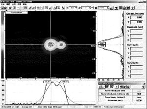
    Figure 7.  Measure diagram of axis misalignment

    通过改变接收端插入塞尺的厚度h,改变光轴夹角α。在透镜像方焦点处测量发射和接收光斑质心坐标Ot, Or以及光斑重合面积Sr, t和光束接收效率η,如表 2所示。

    h/mm Ot/μm Or/μm Sr, t/mm2 η
    0.01 (705.5, 0) (33.2, -16.6) 0.738 0.109
    0.02 (1011.7, 14.4) (47.1, 18.3) 0.196 0.023

    Table 2.  Coupling efficiency with different misalignments and with fixed far position

    塞尺最小厚度h1=0.01mm,此时环行器发射和接收光轴夹角α1=0.74mrad; 当h2=0.02mm时,α2=1.44mrad。由表 2可知,η1=0.109,η2=0.023,可见在同一远场位置,接收效率随光轴夹角的增大而减小,与仿真结果一致。由于实验空间有限,所以将环行器出射光束进行聚焦变换,并将光束分析仪探头固定于透镜像方焦点处,用以测量环行器出射光束在同一远场位置处的光斑数据。为了验证实际工作情况,将环行器与光学天线配合装于雷达系统中进行整机测量。当测量天气晴朗,能见度大于25km时,若环行器偏轴度为0.5mrad,系统只能探测到300m;若将环行器发射端和接收端光轴调到完全重合,系统探测距离可到达1500m。

4.   结论
  • 针对小型化激光测风雷达,阐述了具有光束收发合一功能的环行器工作原理。通过推导目标距离处靶目标上的激光峰值光强,研究了环行器出射光束的光束质量。提出环行器光束接收效率定义,讨论了环行器偏轴度的影响。搭建实验平台测量环行器出射光束相关参量,验证了仿真结果。结果表明,随着出射光束发散半角增大,相同作用距离处的相对峰值光强减小,并且距离越远,光强越小。发散半角从0.043mrad增大到0.053mrad、作用距离从50m增大到1500m时,归一化相对峰值光强从0.924下降到0.013。同时,环行器接收效率随偏轴度增大而减小,偏轴度表现为平移和角度误差,激光测风雷达的探测距离主要受角度误差的影响,mrad量级的偏角会使探测距离减小89.7%。因此,为进一步提高激光测风雷达环行器出射光束质量,应合理增大光学天线准直倍率,并且设计的角度调节结构精度应优于0.1mrad量级。

Reference (14)

Catalog

    /

    DownLoad:  Full-Size Img  PowerPoint
    Return
    Return