Advanced Search

ISSN1001-3806 CN51-1125/TN Map

Volume 41 Issue 2
Mar.  2017
Article Contents
Turn off MathJax

Citation:

Design of coupling device for laser cutting guided by water beam

  • Received Date: 2016-03-31
    Accepted Date: 2016-05-23
  • In order to solve the crack caused by thermal stress during the process of laser cutting for the toughened glass, the FLUENT software was adopted to analysis the water presure and the stability of water beam based on water & laser coupling model, and the optimised parameters were obtained. Then experiment based on the optimised parameters was conducted to verify the anslysis results. The results show that, incision surfaces of both No.1 and No.2 samples are smooth and slot with the width of 100μm under the condition of nozzle diameter 0.4mm, water pressure 20MPa, laser power 48W and cutting speed 20mm/s. Thedesign of coupling device with two water filling nozzles is applicable in the whole process of laser cutting for the toughened glass.
  • 加载中
  • [1]

    SHAO G Zh, WANG Q S, ZHAO H, et al. Thermal breakage of tempered glass facade with down-flowing water film under different heating rates[J]. Fire Technology, 2016, 52(5):563-580.
    [2]

    CHEN J Sh, ZHU L Y, LOU X Ch. Method discussion of glass tempering[J].Material Review, 2012, 26(20):135-138(in Chinese).
    [3]

    CHEN F, AN B J, YANG B Zh. Chemical tempering and perfor-mance analysis of thin glass used for display panel[J].Glass, 2012, 23(5):45-47(in Chinese).
    [4]

    HAN B K, ZHANG Y Ch. Analysis of structural failure of curtain walls used in high-rise buildings[J]. Structural Engineers, 2011, 27(3):51-56(in Chinese).
    [5]

    SONG L X, HU X F. Effects of thermal tempering on strenth of window glass of manned spacecraft[J]. Chinese Space Science and Technology, 1996, 27(4):43-49(in Chinese).
    [6]

    NIELSEN J H, OLESEN J F, POULSEN P N, et al. Simulation of residual stresses at holes in tempered glass:a parametric study[J]. Materials and Structures, 2010, 43(10):947-961.
    [7]

    SHENG X J. The simulation and experimental analysis of laser-controlled thermal stress cutting of alumina ceramic[D]. Shanghai: Shanghai Jiaotong University, 2010: 17-19(in Chinese).
    [8]

    ROBERTO D, RICARDO J Z. Analytical model of dynamic crack evolution in tempered and strengthened glass plates[J]. International Journal of Fracture, 2014, 190(10):75-86.
    [9]

    SALMAN N, SHEIKH M A, LI L, et al. Effect of thermal stresses on chip-free diode laser cutting of glass[J]. Optics and Laser Technology, 2009, 41(5):318-327.
    [10]

    TSAI Ch H, LIN B Ch. Laser cutting with controlled crack and pre-bending applied to LCD glass separation[J]. The International Journal of Advanced Manufacturing Technology, 2007, 32(12):11-13.
    [11]

    WANG X H, YAO J H, ZHOU G B, et al. Research of the techno-logy of laser cutting LCD glass substrates based on thermasl cracking method[J]. Laser Technology, 2011, 35(4):472-476(in Chin-ese).
    [12]

    HOU H L, PENG Y H, XIE Y K, et al. Effect of laser cutting on fatigue performance of aircraft skin[J]. Laser Technology, 2016, 40(3):417-421(in Chinese).
    [13]

    XU G L, LI Y X, HUANG S Y, et al. Parameters model for laser glass cutting[J]. Journal of Huazhong University of Science and Technology (Nature Science Edition), 2007, 35(7):48-50(in Chin-ese).
    [14]

    GAO W Q. Modeling and simulation of fluid field and temperature field coupling system of laser grooving[D]. Jilin: Jinlin University, 2015: 36-39(in Chinese).
    [15]

    SUN Ch T. Research of water guided laser devices and its machining properties[D]. Harbin: Harbin Engineering University, 2006: 16-20(in Chinese).
  • 加载中
通讯作者: 陈斌, bchen63@163.com
  • 1. 

    沈阳化工大学材料科学与工程学院 沈阳 110142

  1. 本站搜索
  2. 百度学术搜索
  3. 万方数据库搜索
  4. CNKI搜索

Figures(9)

Article views(5546) PDF downloads(498) Cited by()

Proportional views

Design of coupling device for laser cutting guided by water beam

  • 1. School of Mechatronic Engineering, Wuyi University, Jiangmen 529020, China
  • 2. School of Applied Physics & Materials, Wuyi University, Jiangmen 529020, China

Abstract: In order to solve the crack caused by thermal stress during the process of laser cutting for the toughened glass, the FLUENT software was adopted to analysis the water presure and the stability of water beam based on water & laser coupling model, and the optimised parameters were obtained. Then experiment based on the optimised parameters was conducted to verify the anslysis results. The results show that, incision surfaces of both No.1 and No.2 samples are smooth and slot with the width of 100μm under the condition of nozzle diameter 0.4mm, water pressure 20MPa, laser power 48W and cutting speed 20mm/s. Thedesign of coupling device with two water filling nozzles is applicable in the whole process of laser cutting for the toughened glass.

引言
  • 钢化玻璃是平板玻璃经加热淬冷处理后形成的,具有抗弯、承载能力强、破裂后无锐角、抗热炸裂等优点[1-2]。其广泛应用于航天飞行器、武器装备、汽车挡风玻璃、电子产品屏幕、高层建筑门窗、家具等[3-5]。由于钢化玻璃具有极高的硬脆性,在激光切割过程中会产生很大的热应力,导致裂纹产生并发生破裂[6-8]。英国SALMAN[9]借助有限元软件ABAQUS分析了激光切割速度对应力的影响,并优化了切割路径。TSAI[10]在用CO2激光切割LCD玻璃时利用应力诱导材料沿切割方向分离,并分析了裂纹的形成机理。浙江工业大学WANG等人[11]采用CO2激光在液晶玻璃基板上预置初始裂纹, 用CO2激光作为热源对其进行加热并用Ar气进行冷却。陕西理工学院HOU等人[12]采用仿真分析法和对比试验法对飞机蒙皮材料的疲劳性能进行了理论分析和实验验证,研究了激光切割对飞机机身蒙皮材料疲劳性能的影响。结果表明, 激光切割对飞机机身蒙皮材料疲劳性能有一定的影响,但通过切缝打磨处理会提高其疲劳寿命。本文中将特定波长的会焦激光束导入高速流动的水束,使激光在水与空气界面发生多次全反射后形成横截面能量均匀分布的高能束射到工件上,与工件材料、水发生复杂的热、力等物理和化学作用以实现切割,可有效弥补目前金刚石切割钢化玻璃的不足。

1.   微水导激光耦合模型
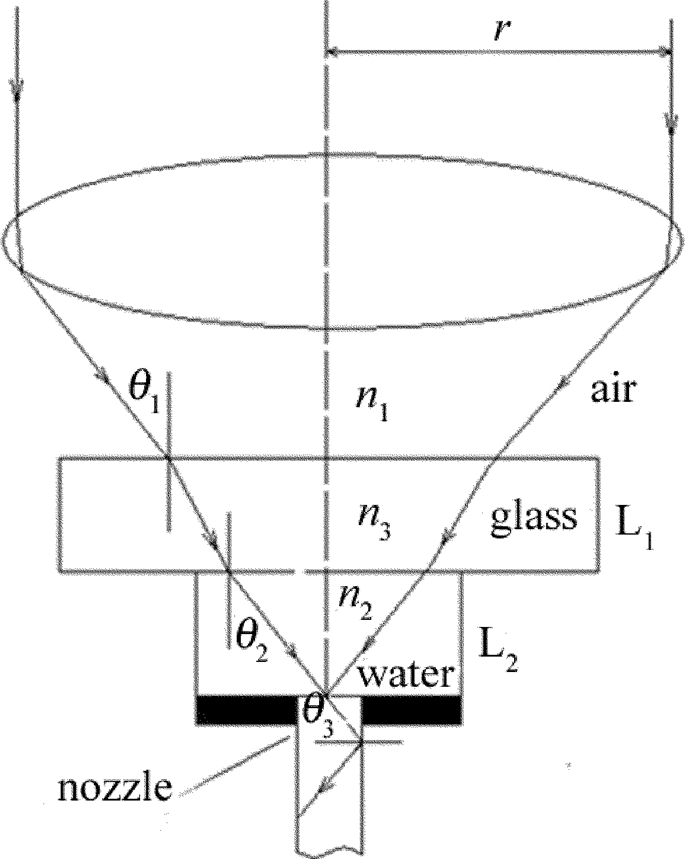
  • 激光耦合即激光束在微水束中发生多次全反射后形成高能量束并在微水束中传输的过程。耦合期间激光束要依次经过空气层、玻璃层L1、水层L2并进入到水束光纤的开始端[13-14],如图 1所示。

    Figure 1.  Sketch map of coupling of laser beam & water beam

    激光光束在水束中发生全反射的条件是入射角θ1不大于最大入射角αmax。由于在耦合过程中,玻璃厚度很薄,假设光线在经由玻璃层时是直线传输,则发生临界全反射时,有:

    图 1可得:

    由(1)式~(4)式,得到:

    式中, n1为激光在空气中的折射率,n2为激光在水中的折射率,C为临界入射角,r为激光束聚焦前的光斑半径,H0为凸透镜焦距。当n1=1,n2=1.33时,由(6)式得到:θ1, max=61.3°。本文中选用r=10mm,H0=50mm,则实际入射角θ1=11.5° < θ1, max,满足激光束全反射的条件。

    第2个重要耦合条件是微水束的稳定性。受水束内外紊乱、水束表面张力、水束速度分布以及周围空气的影响,水束的表面高度呈周期性波动[15],一旦表面波动的振幅超过极限值,被导引的激光将从水束中发散出来。本文中采用FLUENT软件对注水口数量、耦合腔顶部薄水层压力、耦合器内部流体压力对喷嘴水射流稳定性的影响进行数值分析,保证喷嘴小孔喷射出的微水束射流均匀稳定,破碎长度大。

2.   耦合装置的设计
  • 耦合装置是实现激光与微水束耦合并传输的关键部件。耦合装置主要由喷嘴体、进水孔、O型圈、喷嘴支架等组成,如图 2所示。本文中将喷嘴设计成圆柱形,目的是为了延长微水束的破碎长度。考虑到激光的能量密度比较大,且激光要在喷嘴内部发生全反射,故喷嘴材料选用耐热性比较好的铜。各参量具体数值为:喷嘴长度为10mm,喷嘴直径为0.4mm,耦合间隙为0.4mm。喷嘴体顶部的定位圆柱体6与喷嘴支架4通过螺纹连接,高压水从左右两侧的注水口注入耦合装置,并进入喷嘴体与光学玻璃之间形成的耦合间隙,然后通过喷嘴片上的喷嘴将耦合之后的光液高能束喷射出来。图 3为耦合装置的实物照片。

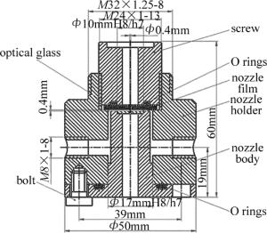
    Figure 2.  Drawing of coupling device

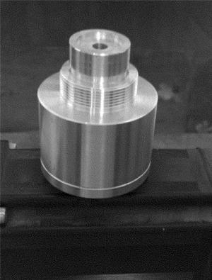
    Figure 3.  Coupling device

3.   耦合腔内流场仿真
  • 耦合腔采用Pro/Engineer进行3维建模,并用GAMBIT软件进行网格划分,网格划分采用Tri-Quad自动生成网格。划分网格后,设置边界,并输出网格文件。用FLUENT软件打开此网格文件,并设计各个参量、求解器及初始条件等,然后进行求解。为了对比不同的注水方式对微水导激光切割质量的影响,进而优化耦合装置的结构,论文依次做了单注水口、双注水口和四注水口的水流场数值模拟。
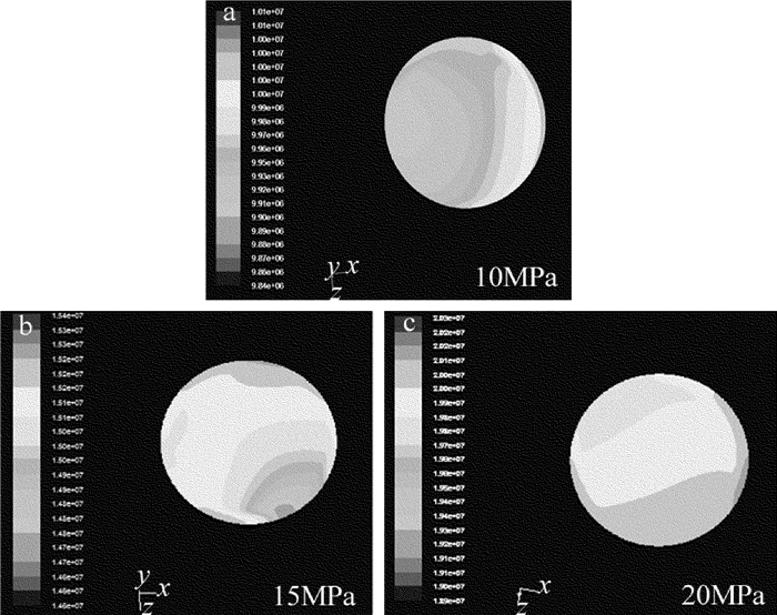
    首先是残差图的收敛计算,设计的收敛参量为1×10⁻³图 4为残差图的收敛计算结果,横坐标为迭代次数,纵坐标为残差值的大小。图 5为单注水口耦合腔顶部水流入口压力分布图,纵坐标为水束压力大小(MPa)。由图 5可以看出:当水束压力为10MPa时,水流入口处压力分布极为不均匀,具有明显的各向异性,且注水口一侧的压力明显较大;随着水束压力的不断增大,水束压力的各向异性逐渐减弱,在水束压力达到20MPa时,入口的水压趋近均匀。

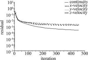
    Figure 4.  Residual diagram

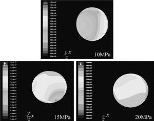
    Figure 5.  Pressure distribution in thin water layer region at the top of coupling cavity in single water injection nozzle

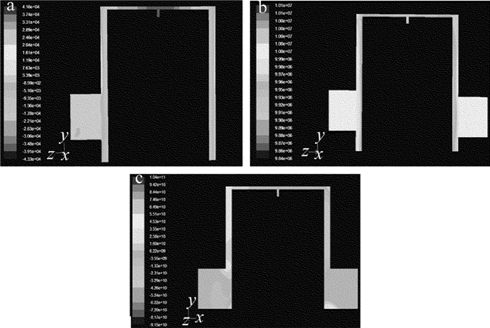
  • 由于单注水口耦合腔得到的水流场并不均匀,注水口的开口位置对顶端薄水层水压的影响较显著,进而影响切割质量。根据流体力学原理,注水口需要对称分布。鉴于此,本文中设计了双注水口的耦合腔和四注水口进行对比优化。其耦合腔流场分别如图 6所示。

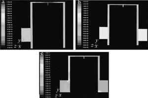
    Figure 6.  Pressure distribution of coupling cavity

    通过对比单注水口、双注水口以及四注水口的水流场数值模拟结果发现,双注水口的压力分布比单注水口的压力分布更均匀,即水流场更为稳定,利于水束与激光束的耦合;四注水口比也双注水口得到的流场稳定,从而验证了耦合装置的理论设计。

  • 经光液耦合后的水束喷射到空气中的情况是比较复杂的。水束会在喷口处发生缩流,水束会突然缩小为原来的80%,然后水束在空气压力的作用下,其直径又慢慢变大,最终导致激光束从水束中逃逸。喷嘴口的大小和水束的流速均会影响喷射流长度,本次仿真选取水束压力为20MPa,依次对0.3mm, 0.4mm及0.5mm 3种口径喷嘴射出的水束稳定性进行仿真,如图 7所示。本次仿真设置的边界为100mm。

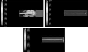
    Figure 7.  Stability simulation of water beam with different nozzle diameter

    仿真结果显示:喷嘴口径越大,水束射流的破碎长度越大,但激光微水束切缝宽度也将越大。在水束压力为20MPa时,口径0.3mm的喷嘴的有效破碎长度约为60mm,口径0.4mm的喷嘴的破碎长度约为80mm,口径0.5mm的喷嘴的破碎长度达到90mm左右。综合考虑各因素,选取喷口口径为0.4mm、水束压力为20MPa、紫外激光功率为48W、重复频率为100kHz,分别对0.5mm及1.0mm厚的钢化玻璃进行微水导激光切割实验验证,切割速率为20mm/s。实验结果显示,厚度为0.5mm及1.0mm的玻璃试样的切割表面均比较光滑、基体内无微裂纹存在,切缝宽度约为100μm,但1.0mm厚的玻璃试样切割边缘有毛刺及崩边现象出现(如图 8所示)。图 9为在实验室已有的HT-3P激光加工系统上进行了一定改造,搭载YPP300光纤激光器,并配置了光液耦合装置。

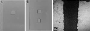
    Figure 8.  Samples after laser cutting

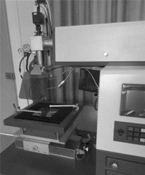
    Figure 9.  HT-3P laser processing system

4.   结论
  • (1) 水压在10MPa~20MPa之间时,薄水层的压力分布随着进水压力的上升而逐渐变得均匀,但是它的水压不够均匀的情况并没有得到根本的改变。水射流仿真时,0.4mm和0.5mm喷嘴得到的射流破碎长度较长,喷嘴越大,水射流长度就越长,但是在达到加工工件的长度要求的情况下,尽量使喷嘴口径最小。

    (2) 在喷口口径为0.4mm、水束压力为20MPa、激光功率为48W、切割速率为20mm/s时进行玻璃的微水导激光切割。厚度为0.5mm及1.0mm的玻璃试样的切割表面均比较光滑、基体内无微裂纹存在,切缝宽度约为100μm,但1.0mm厚的玻璃试样切割边缘有毛刺及崩边现象出现。

Reference (15)

Catalog

    /

    DownLoad:  Full-Size Img  PowerPoint
    Return
    Return