Advanced Search

ISSN1001-3806 CN51-1125/TN Map

Volume 41 Issue 2
Mar.  2017
Article Contents
Turn off MathJax

Citation:

Influence of parameters change on the characteristics of long-range surface plasma wave

  • Received Date: 2016-01-27
    Accepted Date: 2016-03-11
  • In order to acquire the characteristics of long-range surface plasma wave, such as the resonance angle, full width at half maximum of resonance peak and depth of attenuation peak, a prism coupling method was used to excite the long-range plasma surface wave of media-metal film-media symmetrical structure. The influences of the changes of material film material, metal film thickness, medium refractive index, medium thickness and other parameters on the characteristics of long-range surface plasma wave were studied. The results show that, the full width at half maximum of the attenuation peak of long-range surface plasma wave is narrower about 1 or 2 orders of magnitude than that of traditional surface plasma wave. When the dielectric film thickness is 500nm and 1300nm, the attenuation depth of plasma surface wave is only about 1/2 of those of dielectric film thickness 700nm and 1000nm. The full width at half maximum decreases with the increasing of dielectric film thickness. The thinner metal film is, the deeper attenuation depth is, the smaller full width at half maximum of attenuation peak is. The changes of medium refractive index has no obvious influence on full width at half maximum. The various metal film parameters will change the position of resonance peak. The study provides the effective basis for the application of long-range surface plasma wave in sensing, waveguide, and biosensors field.
  • 加载中
  • [1]

    SARID D. Long-range surface-plasma waves on very thin metal films[J]. Physics Review Letters, 1981, 47(26):1927-1930. doi: 10.1103/PhysRevLett.47.1927
    [2]

    DECK R T, SARID D. Enhancement of second harmonic generation by coupling to long-range surface plasmas[J]. Journal of the Optical Society of America, 1982, 72(12):1613-1617. doi: 10.1364/JOSA.72.001613
    [3]

    SHI X L, ZHENG S L, CHI H, et al. All-optical modulator with long range surface plasmas resonance[J]. Optics & Laser Technology, 2013, 49(7):316-319.
    [4]

    SHI H, LIU Z Y, WANG X X, et al. A symmetrical optical waveguide basedsurface plasmas resonance biosensing system[J]. Sensors and Actuators, 2013, B185(8):91-96.
    [5]

    PARK S Y, KIM J T, SHIN J S, et al. Hybrid vertical directional coupling between a long range surface plasmas polariton waveguide and a dielectric waveguide[J]. Optics Communications, 2009, 282(23):4513-4517. doi: 10.1016/j.optcom.2009.08.038
    [6]

    CAO Z Q. Guided wave optics[M]. Beijing:Science and Technology Press, 2007:144-146(in Chinese).
    [7]

    SLAVIK R, HOMOLA J. Ultrahigh resolution long range surface plasmas-based sensor[J]. Sensors and Actuators, 2007, B123(1):10-12.
    [8]

    NENNINGER G G, HOMOLA J, YEE S S. Long range surface plasmas for high resolution surface plasmas resonance sensors[J].Sensors and Actuators, 2001, B74(1):145-151.
    [9]

    TAN X X, WANG G J, WANG Zh B. Opened suspended core fiber chip based on surface plasma resonance enhancement mechanism[J]. Laser Technology, 2016, 40(2):209-212(in Chinese).
    [10]

    HU M Y, ZHU X, QI L J. Numerical simulation of Otto structure in surface plasma wave light modulator[J]. Laser Technology, 2005, 29(3):325-327(in Chinese).
    [11]

    LI Y X, LIU F, HUANG Y D, et al. Coupling between second-order mode in dielectricwaveguide and fundamental mode in long range surface plasmas waveguide[J]. Optics Communications, 2013, 289(2):60-63.
    [12]

    GUO X W, DONG Q M. Long range surface plasmas interference lithography[J].Microelectronic Engineering, 2011, 88(8):2184-2187. doi: 10.1016/j.mee.2011.01.006
    [13]

    KRUPIN O, WANG C, BERINI P. Selective capture of human red blood cells based on blood group using long-range surface plasmas waveguides[J]. Biosensors and Bioelectronics, 2014, 53(3):117-122.
    [14]

    SUI G R, CHENG L, CHEN L. Large positive and negative lateral optical beam shift due to long-range surface plasmas resonance[J]. Optics Communications, 2011, 284(6):1553-1556. doi: 10.1016/j.optcom.2010.10.091
  • 加载中
通讯作者: 陈斌, bchen63@163.com
  • 1. 

    沈阳化工大学材料科学与工程学院 沈阳 110142

  1. 本站搜索
  2. 百度学术搜索
  3. 万方数据库搜索
  4. CNKI搜索

Figures(7)

Article views(4588) PDF downloads(341) Cited by()

Proportional views

Influence of parameters change on the characteristics of long-range surface plasma wave

  • 1. School of Electronic and Electrical Engineering, Shanghai University of Engineering Science, Shanghai 201620, China
  • 2. School of Optical-Electrical and Computer Engineering, University of Shanghai for Science and Technology, Shanghai 200093, China

Abstract: In order to acquire the characteristics of long-range surface plasma wave, such as the resonance angle, full width at half maximum of resonance peak and depth of attenuation peak, a prism coupling method was used to excite the long-range plasma surface wave of media-metal film-media symmetrical structure. The influences of the changes of material film material, metal film thickness, medium refractive index, medium thickness and other parameters on the characteristics of long-range surface plasma wave were studied. The results show that, the full width at half maximum of the attenuation peak of long-range surface plasma wave is narrower about 1 or 2 orders of magnitude than that of traditional surface plasma wave. When the dielectric film thickness is 500nm and 1300nm, the attenuation depth of plasma surface wave is only about 1/2 of those of dielectric film thickness 700nm and 1000nm. The full width at half maximum decreases with the increasing of dielectric film thickness. The thinner metal film is, the deeper attenuation depth is, the smaller full width at half maximum of attenuation peak is. The changes of medium refractive index has no obvious influence on full width at half maximum. The various metal film parameters will change the position of resonance peak. The study provides the effective basis for the application of long-range surface plasma wave in sensing, waveguide, and biosensors field.

引言
  • 长程表面等离子体波(long-range surface plasma wave, LRSPW)是一种特殊的表面波, 若满足波矢匹配条件, 当介质-金属薄膜-介质结构中的两介质折射率接近, 金属薄膜足够薄, 则传播在金属薄膜上下两层界面上的表面等离子体波相互耦合, 产生长程表面等离子体波[1-6]。长程表面等离子体波的共振峰半宽度比普通的表面等离子体波的共振峰半峰全宽(角宽)窄得多, 因此相对于普通的表面等离子体波来说, 其共振角谱对角度和膜厚度以及金属表面的情况更加的敏感[7-10]

    本文中研究棱镜耦合角度调制的方法激发长程表面等离子体波时, 金属膜材料及厚度、介质折射率, 介质厚度等因素对长程表面等离子体波特性的影响, 为长程表面等离子体波的激发以及应用于传感领域提供有效依据[11-14]

1.   基本理论
  • 长程表面等离子体波的激发方式为棱镜耦合激发介质-金属-介质的对称结构, 如图 1所示。棱镜的介电常数为ε0εp, ε0为真空介电常数, εp为棱镜的相对介电常数。图中金属薄膜的厚度为d1, 设金属薄膜及其上下介质(指非金属介质:电介质、空气等)都是非磁(相对磁导率μr=1)的各向同性介质, 它们的介电常数分别记为ε0εmε0εc, εm为金属的相对介电常数, εc表示金属两测介质的相对介电常数, 其中εm=εm,r+jεm,i是复数。金属膜上方介质膜的厚度为d2, 下方介质的厚度可认为半无限大, x=-d1x=0的面是金属与介质的两个界面。若要激发表面等离子波, 则入射光波的模式需为TM模式(Hy, Ex, Ez)。设入射偏振光在棱镜底面与法线的夹角(简称入射角)为θp

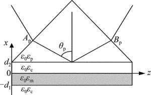
    Figure 1.  System of long-range surface plasma wave excited by prism coupling

    设沿z传播的TM波的磁场强度分布为:

    式中, ω代表光频, β代表磁场沿着z轴方向的传播常数; A, B分别表示入射波磁场和反射光波磁场的振幅, ${k_0} = \frac{{2{\rm{ \mathsf{ π} }}}}{\lambda }, {\alpha _{\rm{p}}} = \sqrt {{\beta ^2} - {k_0}^2{\varepsilon _{\rm{p}}}} , {\alpha _{\rm{c}}} = \sqrt {{\beta ^2} - {k_0}^2{\varepsilon _{\rm{c}}}} , {\alpha _{\rm{m}}} = \sqrt {{\beta ^2} - {k_0}^2{\varepsilon _{\rm{m}}}} $; 下标p, c和m分别表示棱镜、介质和金属。波动方程由下式给出:

    根据TM模在x=-d1, x=0, x=d2界面上的电磁场连续条件, 可得出反射率公式:

    式中, rc,m,crc,p分别表示相应层的菲涅耳系数, 可由菲涅耳公式计算得出, 其值为:

    当棱镜材料的折射率足够大, 从而通过调整棱镜底面的入射角使入射光(TM模式)在界面方向的波矢分量等于表面等离子体波的波矢(即满足波矢匹配条件), 长程表面等离子体波可以被激发。由(3)式可以看出, 金属膜材料及厚度、介质厚度和折射率n的小范围变化都将对反射率造成影响。

2.   实验
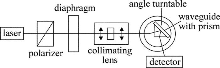
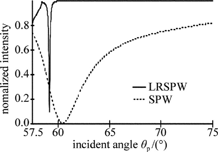
  • 采用波长为632.8nm的He-Ne激光器作为光源, 底角为45°的ZF6材质的直角棱镜, 分别激发传统结构和介质-金属薄膜-介质组成的对称结构。采用图 2所示的系统进行测试, 激光器发出的光经过偏振器产生TM模式的偏振光, 经光阑、准直透镜组后, 入射到棱镜中, 采用光功率计检测出射光的光强, 采用测角转盘来实现入射角度的测量, 入射角的范围为θp=57.5°~75°。传统结构中在棱镜斜边上镀50nm的金膜, 被测介质是质量分数为0.25的NaCl溶液, 在632.8nm时, 其折射率为1.3792。采用棱镜耦合方法激发介质-金属薄膜-介质中的长程表面等离子体波时, 介质采用聚甲基丙烯酸甲酯(polymethyl methacrylate, PMMA)薄膜, 在632.8nm波长下的折射率为1.49, 其厚度为d2=1000nm; 金属采用金膜d1=15nm, 在632.8nm时的折射率为nAu=0.19609+j3.2558。测得的归一化光强与角度变化曲线如图 3所示。图中横轴为入射角度, 纵轴是反射光的归一化光强, 由于测得的光强值较小, 因此做归一化处理, 其值没有单位。从图中可以看出, 当采用棱镜耦合的方式来激励PMMA-金属薄膜-PMMA结构时, 产生的衰减峰的半峰全宽比传统的棱镜耦合的方式激励金属薄膜-被测介质的半峰全宽小得多, 即其衰减峰更加尖锐, 说明此时的损耗比传统的表面等离子体波(surface plasma wave, SPW)的损耗要小得多, 因此能够传输更长的距离, 所以, 也把这种表面等离子体波称为长程表面等离子体波, 其对于角度和膜厚度以及金属表面的情况更加的敏感。测试结果显示, 长程表面等离子体波的半峰全宽为0.121°, 传统的表面等离子体波的半峰全宽为5.365°。

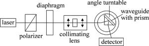
    Figure 2.  Diagram of testing system

    Figure 3.  Comparison of long-range surface plasma wave and the traditional structure

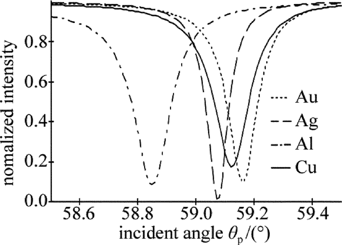
  • 光源与棱镜不变, 激发长程表面等离子体波时, 介质采用PMMA薄膜, d2=1000nm; 金属厚度d1=15nm, 金属薄膜分别采用金膜、银膜、铝膜和铜膜进行测试。在632.8nm时各金属的折射率分别为nAu=0.19609+j3.2558, nAg=0.15677+j3.8045, nAl=0.12667+j7.2811, nCu=0.30703+j3.4345, 入射角范围为θp=58.5°~59.5°, 测得的结果如图 4所示。从图中可以看出, 在激励长程表面等离子体波时, 采用不同的金属材质, 对于衰减峰的位置和半峰全宽都会产生影响, 对于金膜、银膜、铝膜和铜膜, 所对应的共振峰角度分别为59.164°, 59.077°, 58.851°和59.125°, 所对应的半峰全宽分别为0.121°, 0.085°, 0.167°和0.184°。因此铝膜所对应的最大衰减时的入射角度最小, 金膜对应最大衰减峰时的入射角度最大, 银膜对应的衰减峰最尖锐, 且衰减最大。因此, 采用不同的金属薄膜对于长程表面等离子波的衰减峰位置、共振峰的半峰全宽以及衰减峰的深度都有影响, 可以根据需要选择不同的金属薄膜。由于银、铝和铁的化学性质不是特别稳定, 长期与外界接触容易产生氧化, 因此常采用金膜来实现传感应用。

    Figure 4.  Test results of long-range surface plasma wave excited by different metal

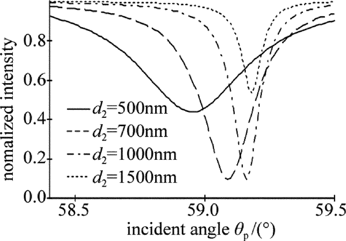
  • 光源和棱镜与前面实验一致, 激发长程表面等离子体波时, 金属薄膜采用金膜, 其厚度d1=15nm, 介质采用PMMA薄膜, 金属薄膜与棱镜之间的介质膜厚度d2分别采用500nm, 700nm, 1000nm和1300nm时, 改变入射角θp, 其变化范围为58.4°~59.5°, 测得的光强随入射角变化的曲线如图 5所示。所对应的共振峰角度分别为58.954°, 59.093°, 59.166°和59.183°。从图 5中可以看出, 激励长程表面等离子体波时, 当棱镜与金属薄膜之间的介质膜厚度不同时, 对于衰减峰的位置、深度及衰减峰的半峰全宽都会产生影响。随着介质膜厚度的增大, 衰减峰对应的共振角度增大。若要取得较大的衰减深度, 则介质膜选择既不能太厚也不能太薄, 当介质膜厚度为500nm和1300nm时, 激发的表面等离子体波的衰减深度只有700nm和1000nm厚度薄膜时的1/2左右。而介质膜的厚度对于长程表面等离子体波的半峰全宽影响较为显著, 当介质膜厚度为500nm时, 半峰全宽的值最大, 1300nm时半峰全宽的值最小。而介质厚度为700nm和1000nm时, 共振曲线具有近似相等的衰减程度, 但介质厚度为1000nm时, 具有较小的半峰全宽值。随着介质膜厚度的增加, 所激发的长程表面等离子体波的半峰全宽减小。

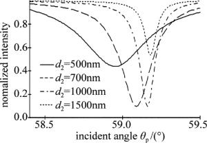
    Figure 5.  Results with the excitation of dielectric film with different thickness

  • 激发长程等离子体表面波时, 保持光源与棱镜不变, 介质采用PMMA膜, 波长为632.8nm时折射率为1.49, 厚度d2=1000nm, 金属薄膜采用金膜, 膜厚d1分别采用10nm, 15nm, 20nm, 30nm时, 改变入射角θp, 其变化范围为58°~62°, 测得的光强随入射角变化的曲线如图 6所示, 分别在58.691°, 59.164°, 59.769°和61.281°处产生最大衰减。从图 6中可以看出, 在激励长程表面等离子体波时, 采用不同的金属膜厚度, 对于衰减峰的位置和衰减峰的半峰全宽都会产生影响, 图中当金膜为10nm的时候, 衰减深度最深, 衰减峰的半峰宽度最小; 而当金属膜为30nm时, 衰减峰非常不明显, 因此, 在激发长程表面等离子体波时, 金属材质越薄, 则衰减深度越深, 衰减峰的半峰全宽值越小, 当金属膜厚度大于20nm时, 激励的长程表面等离子体波的衰减峰不明显, 这是由于金属膜上下与介质接触界面表面波的耦合产生了长程表面等离子波, 当金属薄膜越厚时, 产生的耦合效应越小。

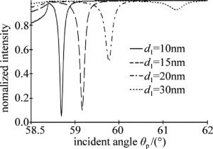
    Figure 6.  Results with the excitation of metal film with different thickness

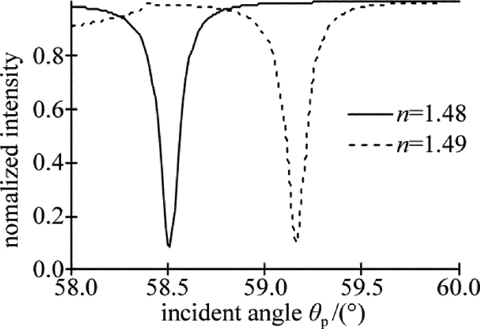
  • 实验中的光源和棱镜与前面实验一致, 在激发长程表面等离子体波时, 采用金膜, 膜厚为15nm, 介质膜膜厚d2=1000nm, 当介质膜折射率n分别为1.48和1.49时, 改变入射角θp, 其变化范围为58°~60°, 测得的光强随入射角变化的曲线如图 7所示。分别在58.571°和59.163°产生最大衰减, 从图中可以看出, 在激励长程表面等离子体波时, 当介质折射率变化时, 衰减峰的位置发生变化, 随着介质折射率的增大, 衰减峰的位置向着大角度方向移动, 而介质折射率的改变对于半峰全宽的影响不明显。

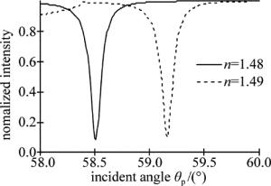
    Figure 7.  Results with the excitation of dielectric film with different refractive index

3.   结论
  • 本文中通过棱镜耦合激发介质-金属-介质结构中的长程等离子体表面波, 研究了传统表面等离子体波与长程表面等离子体波的对比, 其衰减峰半宽比传统的窄1~2个数量级, 通过改变金属膜材质和厚度、介质层厚度及折射率等参量时长程表面等离子体波谱线的变化, 研究了这些参量改变对长程表面等离子体波的衰减峰位置、衰减深度及半峰全宽等特性的影响, 为激发长程表面等离子体波及长程表面等离子体波用于传感器的设计提供了有效依据。

Reference (14)

Catalog

    /

    DownLoad:  Full-Size Img  PowerPoint
    Return
    Return