Advanced Search

ISSN1001-3806 CN51-1125/TN Map

Volume 41 Issue 2
Mar.  2017
Article Contents
Turn off MathJax

Citation:

Design and experimental study of radio frequency excited rectangle waveguide CO2 laser

  • Corresponding author: TAN Rongqing, rongqingtan@163.com
  • Received Date: 2016-03-07
    Accepted Date: 2016-04-01
  • In order to research and develop compact radio frequency(RF)-excited waveguide laser and study the factors affecting laser output performance, a compact RF-excited rectangle waveguide CO2 laser was designed and developed by using parallel plane resonator and inner electrode structure. Output mirror of transmissivity 20% was used in the experiment. Under the gas pressure of 14kPa, laser power is up to 12W and the optimal electron-photon conversion efficiency reaches 9.4%. The results show that gas pressure and input power are the main factors affecting laser output performance. The experimental results achieve the expected experimental results and provide technical references for the development of this type of appliance.
  • 加载中
  • [1]

    HALL D R, BAKER H J. Area scaling boosts CO2 laser performance[J]. Laser Focus World, 1989, 10(3):77-82.
    [2]

    XIN J G, WEI G H. RF excited diffusively cooled CO2 laser technique development and prospect[J]. Chinese Laser, 1994, 21(5):371-376(in Chinese).
    [3]

    YAO S N. A review of CO2 waveguide laser development and its prospect[J]. Journal of Beijing Union University (Natural Sciences Edition), 2008, 22(3):9-12(in Chinese).
    [4]

    GUO Z H, XU D S. Power unit controller for RF-excited CO2 laser[J]. Laser Technology, 1999, 23(3):156-158(in Chinese).
    [5]

    CHEN L, YANG Y Q. Laser cleaning technology and its application[J]. Infrared and Laser Engineering, 2004, 33(3):274-277(in Chinese).
    [6]

    LI F, WU S Y, ZHENG Y C, et al. Overview of the development of synthetic aperture lidar[J]. Infrared and Laser Engineering, 2006, 35(1):55-59(in Chinese).
    [7]

    LIU Y H. Devising of an inner hydro-cooling circulation system of RF-excited the all metal CO2 waveguide laser[J]. Journal of Northwest University (Natural Science Edition), 2013, 43(3):400-402(in Chinese).
    [8]

    ZHOU B K. Principles of laser[M]. Beijing:National Defence Industry Press, 2009:132-161(in Chinese).
    [9]

    MA Y W, CHEN Y Q. Laser devices[M]. Hangzhou:Zhejiang University Press, 1994:51-73(in Chinese).
    [10]

    HILL C A, HALL D R. Coupling loss theory of single-mode waveguide resonators[J]. Applied Optics, 1985, 24(9):1283-1290. doi: 10.1364/AO.24.001283
    [11]

    DEGNAN J J, HALL D R. Finite-aperture waveguide lasers resonators[J]. Optical and Quantum Electronics, 1973, 31(9):901-910.
    [12]

    JEAN L B, GOVIND P A. Mode discrimination and coupling losses in rectangular-waveguide resonators with conventional and phase-conjugate mirrors[J]. Journal of the Optical Society of America, 1982, 72(7):853-860. doi: 10.1364/JOSA.72.000853
    [13]

    LIU Y H, TANG L X. Design and technique of RF-excited metal-ceramic rectangle waveguide CO2 laser[J]. Laser & Infrared, 2010, 40(4):370-372(in Chinese).
    [14]

    ZHANG D L, CAO F G, HAN Y S, et al. Study on the relationship between the power and the frequency of CO2 laser excited by RF[J]. Laser Technology, 2005, 29(2):199-200(in Chinese).
    [15]

    YAO S N, SU N, XIN J G. An experimental study of RF excited diffusively cooled all-mental rectangle waveguide CO2 laser[J]. Acta Armamentarii, 2006, 27(6):1009-1002(in Chinese).
  • 加载中
通讯作者: 陈斌, bchen63@163.com
  • 1. 

    沈阳化工大学材料科学与工程学院 沈阳 110142

  1. 本站搜索
  2. 百度学术搜索
  3. 万方数据库搜索
  4. CNKI搜索

Figures(7)

Article views(7208) PDF downloads(310) Cited by()

Proportional views

Design and experimental study of radio frequency excited rectangle waveguide CO2 laser

    Corresponding author: TAN Rongqing, rongqingtan@163.com
  • 1. Institute of Electronics, Chinese Academy of Sciences, Beijing 100190, China
  • 2. University of Chinese Academy of Sciences, Beijing 100190, China

Abstract: In order to research and develop compact radio frequency(RF)-excited waveguide laser and study the factors affecting laser output performance, a compact RF-excited rectangle waveguide CO2 laser was designed and developed by using parallel plane resonator and inner electrode structure. Output mirror of transmissivity 20% was used in the experiment. Under the gas pressure of 14kPa, laser power is up to 12W and the optimal electron-photon conversion efficiency reaches 9.4%. The results show that gas pressure and input power are the main factors affecting laser output performance. The experimental results achieve the expected experimental results and provide technical references for the development of this type of appliance.

引言
  • 自从1989年HALL等人首次提出射频(radio frequency, RF)激励扩散冷却面增比波导CO2激光器技术以来[1],射频波导CO2激光器技术发展迅猛,这得益于射频激励波导CO2激光器有着激励电压低、输出功率高、寿命长、结构紧凑、易于快速调制、多个波导可共用激励电源、对恶劣环境适应性强等这些优点[2-3]。由于射频波导CO2激光器的诸多优点,使其在激光加工、激光标记、激光雷达以及激光与物质相互作用等领域有着广泛的应用[4-6]。目前,国内市场的中小功率射频波导CO2激光器仍然以进口为主,国内研发的产品存在着激光输出不稳定、光电转换效率不高、结构较为复杂等问题[7]。作者自主设计并研制了一台紧凑型射频激励矩形波导CO2激光器,波导腔尺寸为1.5mm×3mm×434mm,采用平行平面波导腔结构,获得了12W的连续激光输出,光电转换效率达到9.4%。

1.   损耗分析
  • 根据波导腔模理论[8-9],在矩形波导激光器中,只存在EHmn模,其中EH11模为最低阶损耗模,也是最主要的模式。EH11模在矩形波导谐振腔内传输损耗很小,可忽略不计。当光波从波导口向自由空间传播时,经反射镜反射再返回波导口的过程中,由于光场受到扰动,只有一部分能量返回波导口,其中又只有一部分能量耦合到同一模中去,这就产生耦合损耗。耦合损耗是波导腔最主要的损耗,也是要尽量减少的损耗。通过对波导腔耦合损耗的研究[10-12],发现耦合损耗在以下3种情况下最低:(1)平面镜或接近平面镜的大曲率半径反射镜紧挨波导口,对应于平行平面结构;(2)曲率半径较小的反射镜,其曲率半径的一半等于波导口到反射镜的距离,对应于半共焦结构;(3)曲率半径较大的反射镜且反射镜到波导口的距离差不多等于反射镜的曲率半径,也就是说反射镜的曲率中心几乎位于波导口处,对应于半共心结构。

    作者采用第1种平行平面结构,将全反镜和输出镜都紧贴波导口放置,其中全反镜为平面铜镜,输出镜为曲率半径15m的ZnSe镜片,这样波导腔的耦合损耗很小,几乎可以忽略。另外, 作者利用氧化铝陶瓷良好的导热性以及上下电极优良的散热设计来尽量减少由温度变化引入的损耗[13]。此外,作者还尽可能提高波导内壁的光洁度,使得波导腔的损耗尽可能地降到最小。

2.   激光器结构
  • 激光器的外部结构示意图如图 1所示。激光器的腔体外壳为铝合金外壳,前端面和后端面里面分别放置输出镜和全反镜,全反镜为平面铜镜,输出镜为ZnSe镜片,曲率半径为15m,透过率为20%。用分子泵把激光器腔体抽成真空后,将CO2等混合气体从充气口充入腔体。射频激励源连接射频馈入端,对激光器进行射频激励,在射频源和激光器之间还连接有匹配耦合电路。

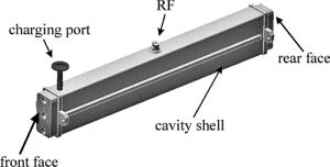
    Figure 1.  Schematic diagram of exterior structure of laser

    图 2为激光器的内部截面示意图。电极采用内电极结构,上下电极板具有扩散冷却的作用。在上下电极板之间夹杂着若干片95%的Al2O3陶瓷垫片,这种95氧化铝陶瓷是目前国内外微波器件和大功率器件最常用的材料,它具有强度高、高频损耗小、热电性能优越等特点,对制造激光器件提供了可靠的技术保证,同时还起着支撑保护的作用。在上下电极和腔体外壳之间也垫有若干片Al2O3陶瓷垫片。该激光器的一个核心部件就是波导腔,波导腔的尺寸为1.5mm×3mm×434mm,全反镜和输出镜都紧贴波导口。

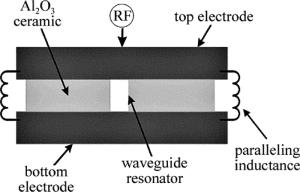
    Figure 2.  Schematic diagram of internal cross section of laser

3.   实验结果和分析
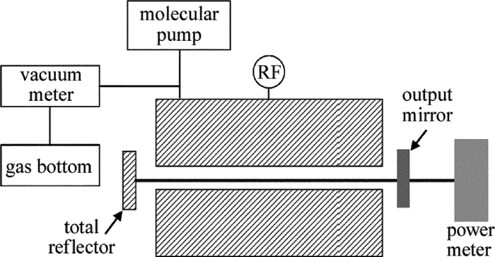
  • 实验装置示意图如图 3所示。用分子泵把激光器腔体抽成真空之后,从气瓶里把气体混合为体积比为V(CO2):V(N2):V(He):V(Xe)=1:1:2:0.25的混合气体充入谐振腔,通过真空计检测充入气体的气压,用射频激励源对激光器进行激励放电,然后用功率计测量输出激光的功率。其中射频电源频率为81.36MHz[14]

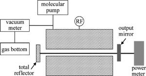
    Figure 3.  Schematic diagram of experimental equipment

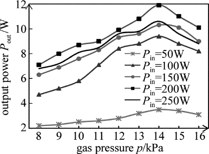
    实验中测得在不同的射频输入功率Pin下,激光输出功率Pout和工作气压p的关系,如图 4所示。由图 4可以看出,对于一定的射频输入功率,激光输出功率先是随着工作气压的增大而增大,到达某个最佳气压值时,输出功率达到最大,此后气压再增大,输出功率开始有明显下降,而且可以看出工作气压的最佳值在14kPa左右。其中,在射频输入功率Pin=200W、工作气压p=14kPa下,激光输出功率最大值达到12W。

    Figure 4.  Relationship between output power and gas pressure

    图 5中可以看出不同工作气压条件下射频输入功率Pin和输出功率Pout的关系。在一定的工作气压条件下,输出功率随着射频输入功率的增大而增大,当达到某个最大值后,随射频输入功率的增大反而输出功率减小。这是因为输入功率较低时,增益介质没有被充分激励,致使输出功率较低;但当输入功率大于最佳值时,过多功率地注入,导致等离子体介质的阻抗降低,引起E/p值降低(E为电场大小,p为工作气压压强),影响输出功率[15]。另一方面,射频输入功率过高,导致工作气体温度升高,也对输出功率的减小产生一定的影响。从图中还可以看出,在不同的工作气压下,激光输出功率都是在射频输入功率为Pin=200W左右时达到最大。

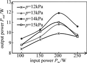
    Figure 5.  Relationship between output power and input power

    图 6则描述了在不同工作气压下,电光转换效率随射频输入功率变化的情况。从图 6可以看出,在工作气压一定的情况下,电光转换效率随着射频输入功率的不同而变化,且在射频输入功率Pin=100W、工作气压p=14kPa时,电光转换效率达到最佳的9.4%。另外,不论在哪种气压下,电光转换效率都是在输入功率为100W左右时达到最大,这与得到最大输出功率所对应的最佳输入功率值是不一样的。

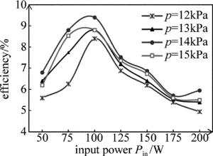
    Figure 6.  Relationship between efficiency and input power

    实验中作者还测量了激光输出的稳定性,在射频输入功率Pin=200W、工作气压p=14kPa下,得到了激光输出功率随时间的变化情况,如图 7所示。作者每5min测一下数据,发现在测量的前35min内,激光输出稳定,输出功率变化幅度很小,浮动范围为(11.4-11.0)/11.2≈3.58%。而在第40min时,输出功率有了比较大的浮动,这是因为工作气体的温度在很大程度上影响了输出功率的大小,而激光器工作时间长了以后,工作气体得不到有效的冷却,导致输出功率的降低。若在扩散冷却的基础上,结合水冷管道的水冷作用,可以达到很好的冷却效果。实验结果表明,与市面上大多数国产的射频波导CO2激光器(输出功率浮动范围在5%以上)相比,该激光器有着较好的输出稳定性。

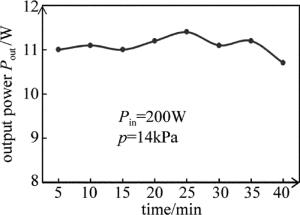
    Figure 7.  Relationship output power and time

4.   结论
  • 设计并制作了一台紧凑型的射频激励矩形波导CO2激光器,波导腔尺寸为1.5mm×3mm×434mm,采用透过率为20%的输出镜,获得最大激光输出功率12W,最佳电光转换效率为9.4%。与市面上大多数国产的射频波导CO2激光器(输出功率浮动范围在5%以上)相比,该激光器输出稳定性较好。其中,工作气压和射频输入功率是影响激光输出性能的最主要的因素。

    该项研究提高了实验研究的主动性并取得了预期的实验结果,对国内今后此类器件的研究具有很好的借鉴意义,对于打破国外对中小功率射频波导CO2激光器市场的垄断增强了信心。

Reference (15)

Catalog

    /

    DownLoad:  Full-Size Img  PowerPoint
    Return
    Return