 网站地图
网站地图

 下载:
下载:
-
光纤干涉型传感器属于相位调制型传感器的一种,通过把待测信号调制在光载波信号的相位上,同时经过一系列运算,便可在输出端完成对待测信号的解调。光纤干涉型传感器采用光学器件作为主要的传感单元,同时采用低损耗的光纤作为系统的传输链路,因此相比于传统的机械型传感器和电学传感器,光纤干涉型传感器具有动态范围大、灵敏度高、抗电磁干扰能力强等优点[1-3],在水声探测、石油勘探、国防科技等领域[4-5]都发挥着重要的作用。
相位生成载波技术(phase generated carrier, PGC)是一种零差解调技术[6-9],现已被广泛应用于光纤干涉型传感器的信号检测中。采用该技术进行相应信号的解调,不但有利于信号的远距离传送和系统全光化的实现,同时还具有灵敏度高、线性度好等优点。传统的PGC解调技术主要包括微分交叉相乘(differential cross multiplication, DCM)算法[10-11]和反正切[12-14] (actangent, arctan)算法两种。其中,PGC-DCM算法的工作性能受光强影响较大[15],解调信号的稳定性比较差,需要对输出的信号进行自动增益控制(auto gain control, AGC),在此基础上,PGC-arctan算法有效克服了这一缺陷,但其解调结果对于调制深度C值仍然具有很强的依赖性,C值一旦发生改变极易引起谐波失真现象,因此,传统的PGC解调技术在实际应用中仍存在着许多不足。针对不同情况,研究学者们相继提出了多种改进算法来进行相应的优化。2010年,HE等人[16]提出了一种PGC反正切微分自交叉相乘(PGC-arctan-DCM)算法,该算法在解调结果中消去了与光强相关的量,相比DCM算法大大增强了系统的稳定性,同时也在一定程度上消除了谐波失真;2012年,LI等人[17]提出了一种基频混频算法,即只采用一路基频信号进行混频,解决了传统算法中系统需要较高的采样率的问题,但该算法只能用于小信号解调,导致系统测量的动态范围受限;2014年,ZHANG等人[18]提出了改进的基频混频解调算法,通过引入直流滤波器来消除信号的直流分量对解调结果的影响;2018年,SUN等人[19]提出了一种改进的相位生成载波解调算法,利用滤去直流量的干涉信号及其与基频相混频的信号来进行运算,有效消除了光源扰动和直流分量对系统的影响,突破了只适用于小信号解调的限制,但解调结果受调制深度的影响仍然较大。
本文中基于相位生成载波技术,在传统PGC解调算法的基础上提出了一种改进算法,通过将输入信号进行微分交叉相除等运算,大大降低了解调结果对于调制深度的依赖。对改进算法进行了相应的仿真,采用正弦信号来模拟待测信号,并将改进算法与PGC传统算法进行了对比,同时当调制深度在一定范围内发生变化时对改进算法的解调效果进行了相应分析。
-
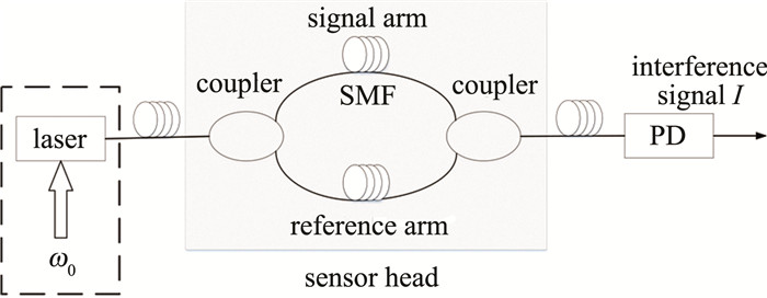
PGC调制技术主要有外调制和内调制两种。外调制中的相位调制可通过调制干涉仪中由光纤缠绕在压电陶瓷环[20]上构成的相位调制器来完成,可以使输入光信号的相位按照一定规律发生变化。内调制技术不需要将调制信号加在调制器上,而是将其直接加载在激光器上,然后通过非平衡干涉仪实现相位生成载波,内调制不需要在调制干涉仪中添加任何器件,对于实现系统的全光化起着重要作用,但是由于内调制需要改变激光器内部的振荡参量,因此要求使用的光源可调频。图 1为内调制型马赫-曾德尔(Mach-Zehnder)光纤干涉仪的基本结构。图中, laser为光源,coupler为耦合器,SMF(single-mode fiber)为单模光纤,signal arm为信号臂,reference arm为参考臂,PD(photodetector)为光电探测器。
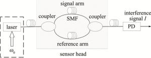
Figure 1. Basic structure of internal modulation type Mach-Zehnder optical fiber interference sensor
上述Mach-Zehnder光纤干涉仪结构中,经光电探测器PD响应输出的干涉信号I可表示为[19]:
$ I = A + B{\rm{cos}}[C{\rm{cos}}({\mathit{\omega }_0}t) + \mathit{\varphi }(t)] $
(1) 式中,A是与光纤干涉仪的输入光强、偏振器等的插入损耗有关的直流项;B=kA(k < 1,为干涉条纹的相干度);C表示调制深度;cos(ω0t)为载波信号,ω0为载波信号的角频率;φ(t)为待测信号,可以表示为:
$ \mathit{\varphi }\left( t \right) = D{\rm{cos}}({\mathit{\omega }_s}t) + \mathit{\varphi }(t) $
(2) 式中,D表示待测信号的幅值;ωs为待测信号的角频率;φ(t)为因受外界环境影响而产生的初始相位。将(1)式按照贝塞尔(Bessel)函数展开可以得到:
$ \begin{array}{c} I = A + B\left\{ {[{{\rm{J}}_0}(C) + 2\sum\limits_{k = 1}^\infty {{{\left( { - 1} \right)}^k}{{\rm{J}}_{2k}}\left( C \right) \times } {\rm{ }}} \right.\\ {\rm{cos}}(2k{\mathit{\omega }_0}t)]{\rm{cos}}[\mathit{\varphi }\left( t \right)] - \left[ {2\sum\limits_{k = 0}^\infty {{{\left( { - 1} \right)}^k}{{\rm{J}}_{2k + 1}}(C) \times } {\rm{ }}} \right.\\ \left. {\left. {{\rm{cos}}[\left( {2k + 1} \right){\mathit{\omega }_0}t]]{\rm{sin}}[\mathit{\varphi }(t)} \right]} \right\} \end{array} $
(3) 式中,Jk(C)表示调制深度C的k阶Bessel函数。
-
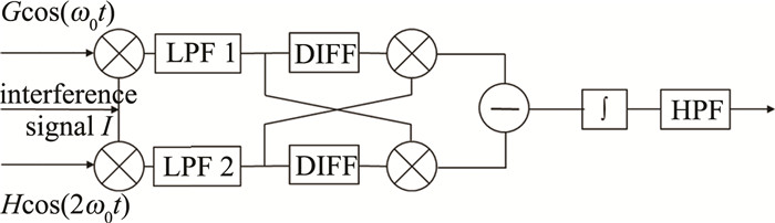
传统的PGC解调算法主要包括DCM算法和arctan算法两种,其中DCM解调原理框图如图 2所示。图中,⊗表示乘法器,LPF(low pass filter)表示低通滤波器,DIFF(differentiator)表示微分器,∫表示积分器,HPF(high pass filter)表示高通滤波器。

Figure 2. Diagram of DCM demodulation
由图 2可知,干涉信号I分别与角频率为ω0、幅度为G和角频率为2ω0、幅度为H的信号发生混频,再通过低通滤波器LPF 1和LPF 2,然后通过LPF 1的信号与经过LPF 2并微分运算后的信号相乘,同时通过LPF 2的信号与经过LPF 1并微分运算后的信号相乘,即可实现两路信号的微分交叉相乘,再对输出的两路信号进行差分和积分运算,经高通滤波后输出的信号最终可表示为[21]:
$ I = {B^2}GH{{\rm{J}}_1}(C){{\rm{J}}_2}(C)\mathit{\varphi }(t) $
(4) 通过上式可以看出,系统最终输出的信号与待测信号之间呈线性关系,由此便可实现对待测信号φ(t)的解调。
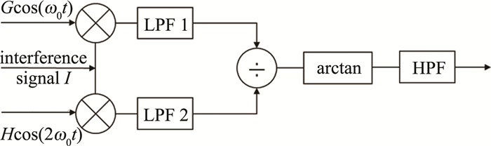
另一种传统的PGC解调算法为arctan算法,其基本原理如图 3所示。
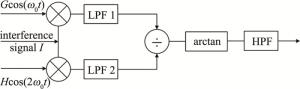
Figure 3. Diagram of arctan demodulation
由图 3可以看出,输入的干涉信号I通过系统,分别与一倍频和二倍频信号发生混频,混频之后分别通过了低通滤波器LPF 1与LPF 2,输出的两路信号进行相除操作后可以得到[16]:
$ \frac{{{I_1}}}{{{I_2}}} = \frac{{G{{\rm{J}}_1}\left( C \right)}}{{H{{\rm{J}}_2}(C)}}{\rm{tan}}\left[ {\mathit{\varphi }(t)} \right] $
(5) 令式中G=H,并调整C值为2.63rad,此时J1(C)= J2(C),通过对上式进行简化便可得到tan$\left[ {\mathit{\varphi }(t)} \right] $的值,进而进行反正切运算,即可得到φ(t)的值,从而完成对待测信号的解调。
-
对于PGC-DCM算法来说,从(4)式所示的解调信号中可以发现,式中含有与调制深度C有关的贝塞尔函数项,这对于解调的准确性以及系统的稳定性都有很大的影响。为了保证输出信号的稳定,通常将调制深度C的值设定为2.37rad,从而使得J1(C)J2(C)取得极大值,此时解调信号受调制深度C的影响相对较小,但是由于外界环境的影响,C值会产生一定的漂移现象,这使得解调信号的幅度仍然会发生变化,影响了系统整体的稳定性。为得到解调信号的值,需要进行如下运算[21]:
$ \mathit{\varphi }\left( t \right) = {\rm{ }}\frac{{{B^2}GH{{\rm{J}}_1}(C){{\rm{J}}_2}(C)D{\rm{cos}}({\mathit{\omega }_\rm s}t)}}{{{\rm{ }}{B^2}GH{{\rm{J}}_1}(C){{\rm{J}}_2}(C)}} $
(6) 当C值发生漂移时,产生的信号会发生一定程度的失真,此时的信号可表示为:
$ \begin{array}{c} {\mathit{\varphi }^\prime }\left( t \right) = {\rm{ }}\frac{{{B^2}GH{{\rm{J}}_1}(C \pm \Delta C){{\rm{J}}_2}(C \pm \Delta C)D{\rm{cos}}({\mathit{\omega }_\rm s}t)}}{{{B^2}GH{{\rm{J}}_1}(C){{\rm{J}}_2}(C)}} = \\ {D^\prime }{\rm{cos}}({\mathit{\omega }_\rm s}t) \end{array} $
(7) 而对于PGC-arctan算法,最终获得的解调结果如(5)式所示,解调的信号仍然受到调制深度C的影响,为了减小失真,需要将C值设定为2.63rad以保证J1(C)=J2(C),从而使得在后续进行反正切运算时解调结果能够保持准确。当由于外界环境扰动导致C的值发生漂移而偏离2.63rad时,此时式中J1(C)≠J2(C),正切函数的系数偏离了1,此时若对信号直接进行反正切运算,输出的解调信号同样会出现波形失真现象。因此,当外界影响造成调制光频漂移以及调制电压的不稳定时,会导致C值发生漂移,进而影响系统解调信号的稳定性,这些对于调制深度的限定条件都在不同程度上大大降低了系统的灵活性。
-
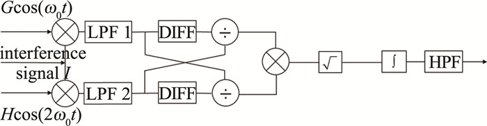
为了解决传统PGC算法中对于调制深度依赖的问题,提出了一种改进的解调算法,其主要的解调原理和系统框图如图 4所示。
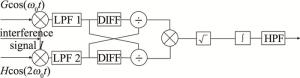
Figure 4. Diagram of improved demodulation algorithm
图 4表明,干涉信号I分别与角频率为ω0、幅度为G和角频率为2ω0、幅度为H的信号发生混频后,经过低通滤波器LPF 1和LPF 2,然后通过LPF 2且经过微分处理后的信号与通过LPF 1的信号进行相除运算,同时通过LPF 1且经过微分处理后的信号与LPF 2的信号进行相除运算,即实现两路信号的微分交叉相除,然后再将交叉相除的两路信号进行相乘操作来消去含有调制深度C的贝塞尔函数项,并对输出信号进行开方和积分运算,最终便可实现对待测信号的解调。干涉信号I与基频和二倍频信号分别混频并通过低通滤波器后的信号可分别表示为:
$ {I_1} = - BG{{\rm{J}}_1}(C){\rm{sin}}\left[ {\mathit{\varphi }(t)} \right] $
(8) $ {I_2} = - BG{{\rm{J}}_2}(C){\rm{cos}}\left[ {\mathit{\varphi }(t)} \right] $
(9) 两路信号分别进行微分运算后得到:
$ \frac{{{\rm{d}}{I_1}}}{{{\rm{d}}t}} = - BG{{\rm{J}}_1}(C){\rm{cos}}\left[ {\mathit{\varphi }(t)} \right]{\mathit{\varphi }^\prime }(t) $
(10) $ \frac{{{\rm{d}}{I_2}}}{{{\rm{d}}t}} = - BG{{\rm{J}}_2}(C){\rm{sin}}\left[ {\mathit{\varphi }(t)} \right]{\mathit{\varphi }^\prime }(t) $
(11) 当G=H时,分别进行交叉相除运算后的两路信号可表示为:
$ \frac{{{\rm{d}}{I_1}/{\rm{d}}t}}{{{I_2}}} = \frac{{{{\rm{J}}_1}(C)}}{{{{\rm{J}}_2}(C)}}{\mathit{\varphi }^\prime }(t) $
(12) $ \frac{{{\rm{d}}{I_2}/{\rm{d}}t}}{{{I_1}}} = \frac{{{{\rm{J}}_2}(C)}}{{{{\rm{J}}_1}(C)}}{\mathit{\varphi }^\prime }(t) $
(13) 为方便后续处理,将(12)式和(13)式分别进行绝对值运算后, 再将两式相乘以达到消去贝塞尔函数项的目的,经上述运算后的式子如下:
$ \left| {\left( {\frac{{{\rm{d}}{I_1}/{\rm{d}}t}}{{{I_2}}}} \right)} \right| \times {\rm{ }}\left( {\frac{{{\rm{d}}{I_2}/{\rm{d}}t}}{{{I_1}}}} \right) = {[{\mathit{\varphi }^\prime }(t)]^2} $
(14) 根据系统流程图,再对上式进行开方运算后得到:
$ \sqrt {{{\left[ {{\mathit{\varphi }^\prime }\left( t \right)} \right]}^2}} = {\mathit{\varphi }^\prime }(t) $
(15) 最后通过积分运算以及高通滤波处理来滤除低频干扰之后便可实现对待测信号的解调:
$ \mathit{\varphi }\left( t \right) = D{\rm{cos}}({\mathit{\omega }_{_\rm s}}t) $
(16) 从最终的解调结果中可以看出,输出的解调信号中只包含待测信号,消除了与调制深度C有关的贝塞尔函数项,使得解调结果摆脱了因C值漂移而带来的影响,提高了系统的稳定性。
-
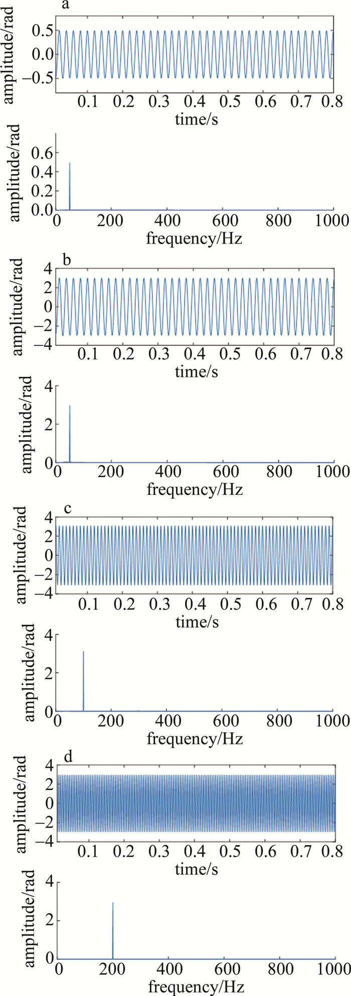
根据改进算法的原理框图,在MATLAB软件中利用相关公式进行不同模块的模拟和计算,主要包括低通滤波器的设计以及微分、开方和积分的数学运算的处理,最终可得到待测信号的解调波形曲线。首先验证了改进算法在解调不同幅值以及不同频率的信号时的仿真结果,干涉信号的形式如(1)式所示,在仿真时,设定A=2,B=1,调制深度(载波信号的幅值)C设置为2.37rad,载波信号的频率为6kHz,待测信号的频率fs分别设置为50Hz, 100Hz和200Hz,振幅D分别设置为0.5rad和3.0rad,系统采样率设置为90kHz,仿真得到的波形与频谱图结果如图 5所示。通过图 5a和图 5b可以观察到,当信号是幅值为0.5rad的小信号时,改进算法可以很好地解调出待测信号,对于幅值为3.0rad的信号,改进算法仍表现出良好的解调效果。同时由图 5b、图 5c和图 5d可知,当待测信号的频率分别为50Hz、100Hz和200Hz时,改进算法的解调效果并没有因信号频率的升高而受到影响,从而验证了该改进算法可以对在一定幅值和频率范围内变化的待测信号进行解调。
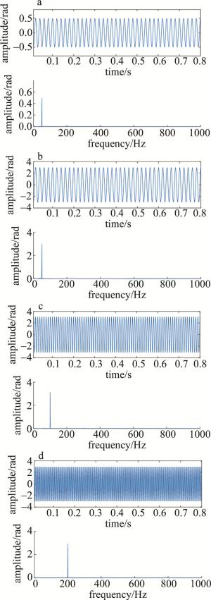
Figure 5. Demodulation results when the amplitude and frequency of the signal under test are different
-
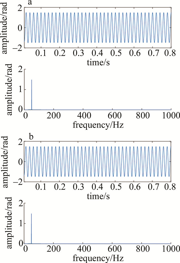
为了表明改进算法在一定程度上解除了对于调制深度的依赖,对采用两种典型调制深度时的干涉信号进行了解调。以频率为50Hz、振幅为1.5rad的余弦信号作为待测信号源,取DCM算法与arctan算法的两个典型的调制深度C值(2.37rad和2.63rad)进行仿真,其余参量保持不变,得到的调制信号仿真结果如图 6所示。由图 6可知,在分别取调制深度C为2.37rad和2.63rad时,仿真结果表明, 在这两个典型的调制深度下,改进算法都能够完成对待测信号的解调。

Figure 6. Demodulation results at typical modulation depths
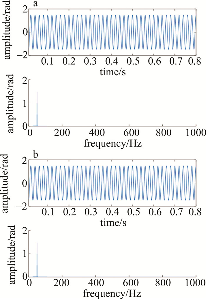
在上述基础上,为了证实当调制深度为非典型值时,改进算法仍然具有普适性,对调制深度为其它值时改进算法的解调情况进行了仿真,同样设定待测信号的频率为50Hz,振幅为1.5rad,调制深度C分别设置为1.5rad和3.0rad,根据解调框图进行计算与仿真,获得的解调结果如图 7所示。由图 7可知,当调制深度分别为1.5rad和3.0rad时,利用改进算法解调得到的信号波形和频谱分量几乎没有变化,由此基本可以确定该改进算法在一定程度上摆脱了对于调制深度的依赖,在系统的灵活性上得到了很大的改善。
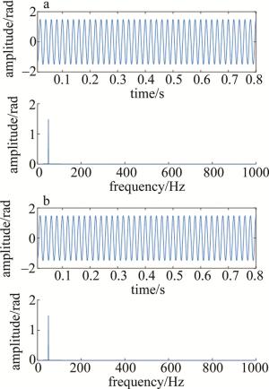
Figure 7. Demodulation results at other modulation depths
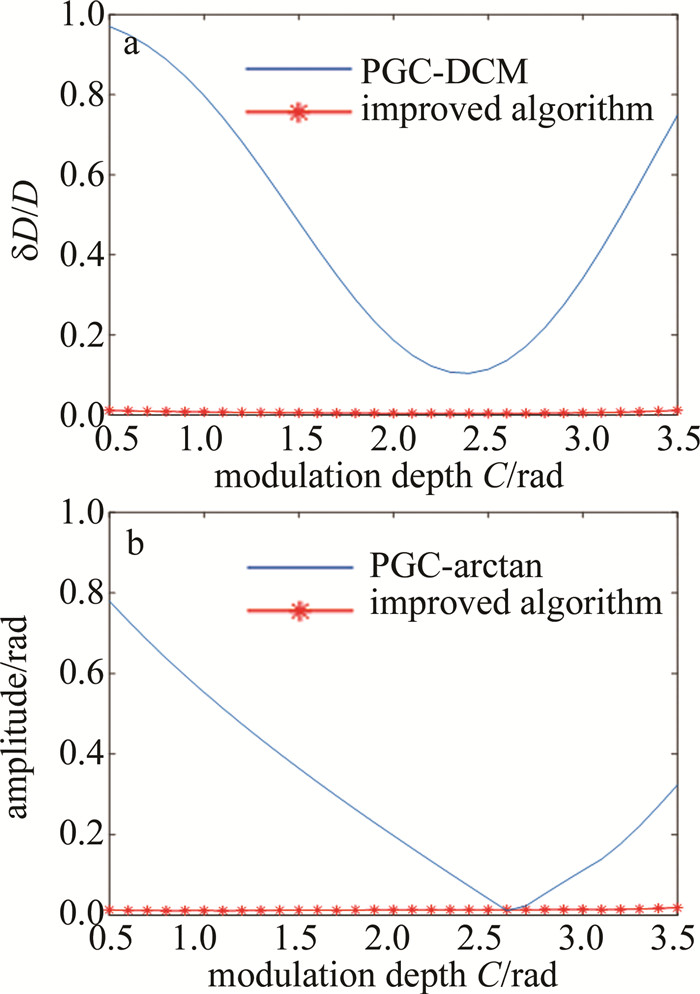
为进一步证明当调制深度发生变化时改进算法的稳定性,对调制深度在0.5rad~3.5rad范围内变化时改进算法与PGC传统算法的信号解调情况进行了仿真对比,图 8a即为分别使用改进算法与PGC-DCM算法时解调得到的信号幅值的变化情况。这里用δD表示解调幅值的变化量,δD/D表示解调信号幅值的失真程度,从图中曲线可以看出,对于PGC-DCM算法,在除了调制深度C=2.37rad以外的值,得到的解调信号幅值相对于原始信号都有很大的变化,传统算法中一般取2.37rad作为系统标定的C值,当外界因素导致C值偏离2.37rad时,根据上文中对调制深度的分析,最终得到的信号幅值为,使得解调信号幅值偏离了待解调信号幅值D而出现失真;对于改进算法来说,当C值在0.5rad~3.5rad范围内发生变化的过程中,改进算法始终保持了解调信号幅度的稳定性,消除了因C值漂移带来的对解调信号幅值的影响。
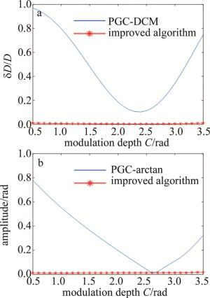
Figure 8. Comparison of improved algorithm and PGC traditional algorithm at different modulation depths
图 8b为使用改进算法与PGC-arctan算法时在不同调制深度下高次谐波分量的变化情况。对于PGC-arctan算法来说,当C值为2.63rad时,解调出的信号除了在待测信号频率处的频谱分量之外,在其它频率处几乎没有频率分量存在,存在较小的谐波失真,而当C值偏离2.63rad时,由于J1(C)≠J2(C),在进行反正切运算之后,在除待测信号频率之外的频率点处也有较大频谱分量,因此产生的谐波失真较为明显;而对于改进算法,从图中可以看出,在C值发生变化的整个过程中,谐波失真量始终保持在一个很小的值。通过上述分析可以证实,相较于两种传统的PGC算法而言,改进算法在选择C值的灵活性上以及抗C值漂移的稳定性上都可以发挥很大的作用。
-
本文中提出了一种区别于传统PGC解调技术的改进算法,利用微分交叉相除与其它运算相结合的方式来实现对待测信号的解调。通过在多种情况下对改进算法进行仿真,结果表明,该改进算法在解调不同幅值与频率的信号时,能够无失真地恢复原待测信号;其次,将改进算法应用在不同调制深度的条件下,并对解调出的信号进行分析,发现当调制深度在0.5rad~3.5rad的范围内变化时,改进的解调算法能够始终保持解调结果的稳定与不失真,即证明该算法能够很好地消除调制深度对于解调结果的影响。所提出的改进算法可以有效降低系统对于调制深度的依赖,消除了由于C值漂移产生的谐波失真现象,同时该算法可以对在一定幅值和频率范围内变化的待测信号实现解调,大大提高了系统的稳定性和灵活性。本文中主要在仿真层面进行了算法理论的验证与分析,在以后的研究中也将会采用相关的信号处理方法来探究噪声对于系统性能的影响,以提升其实用价值。
光纤干涉传感器相位生成载波解调算法研究
Research on improvement of phase generated carrier demodulation algorithm for fiber optic interferometric sensor
-
摘要: 为了解决传统的相位生成载波解调算法中由调制深度漂移引起的解调结果失真现象,采用微分交叉相除的信号解调方法进行了相关的理论分析及仿真验证,得到了一种不受调制深度限制的高性能相位生成载波解调方案。结果表明,在采用不同幅值和频率的待测信号进行仿真时,改进算法的解调性能始终十分优异;且当调制深度的值为典型值2.63rad和2.37rad以及非典型值1.5rad和3.0rad时,使用该算法得到的解调信号都没有发生失真;同时,当调制深度在0.5rad~3.5rad范围内变化时,与传统解调算法相比,改进算法中解调信号的幅值始终与待测信号保持一致, 且高次谐波分量始终非常小。该研究解决了传统解调算法中调制深度变化带来的失真现象,为光纤干涉型传感系统的解调方案提供了参考。Abstract: In order to solve the distortion of the demodulated signal caused by the drift of modulation depth in the traditional phase generation carrier demodulation algorithms, the signal demodulation method of differential cross division was adopted. Related theoretical analysis and simulation verification were carried out, and a high-performance phase-generating carrier demodulation scheme that was not limited by the modulation depth was obtained. The results show that the demodulation performance of the improved algorithm is always excellent when the signals under test of different amplitudes and frequencies are used for simulation. When the values of modulation depth are respectively typical values such as 2.63rad and 2.37rad and atypical values such as 1.5rad and 3.0rad, the demodulated signals obtained by improved algorithm has no distortion. At the same time, when the modulation depth changes in the range of 0.5rad~3.5rad, compared with traditional demodulation algorithms, the amplitude of the demodulated signal in the improved algorithm is always consistent with the signal under test and the high-order harmonic components are always very small. This research solves the distortion phenomenon caused by the modulation depth change in traditional demodulation algorithms, and provides a reference for the demodulation scheme of the optical fiber interferometric sensor system.
-
Key words:
- sensor technique /
- signal demodulation /
- differential cross division /
- modulation depth
-
Figure 1. Basic structure of internal modulation type Mach-Zehnder optical fiber interference sensor
Figure 5. Demodulation results when the amplitude and frequency of the signal under test are different
a—D=0.5rad, fs=50Hz b—D=3.0rad, fs=50Hz c—D=3.0rad, fs=100Hz d—D=3.0rad, fs=200Hz
Figure 8. Comparison of improved algorithm and PGC traditional algorithm at different modulation depths
a—the amplitude change of demodulated signal under improved algorithm and DCM algorithm b—higher harmonic components of demodulated signal under improved algorithm and arctan algorithm
-
[1] LEE B H, KIM Y H, PARK K S, et al. Interferometric fiber optic sensors[J]. Sensors, 2012, 12(3): 2467-2486. doi: 10.3390/s120302467 [2] LI Y Sh, ZHOU B, LI X Y. Phase modulation and demodulation of interferometric fiber-optic hydrophone using phase generated carrier techniques[J]. Journal of Transducer Technology, 2004, 23(2): 14-17(in Chinese). [3] CAO J N, LI X Y, ZHANG L K, et al. Dynamic range analysis of Mach-Zehnder fiber optic interferometer using PGC homodyne detection scheme[J]. Journal of Harbin Engineering University, 1998, 19(5): 81-87(in Chinese). [4] YIN J, LIU T, JIANG J, et al. Assembly-free-based fiber-optic micro-Michelson interferometer for high temperature sensing[J]. IEEE Photonics Technology Letters, 2016, 28(6): 625-628. doi: 10.1109/LPT.2015.2503276 [5] ZHANG R, JIANG Sh, YAN Q Zh, et al. All-fiber perimeter alarm system based on Mach-Zehnder interference[J]. Laser Technology, 2013, 37(3): 334-337(in Chinese). [6] DANDRIDGE A, TVETEN A B, GIALLORENZI T G. Homodyne demodulation scheme for fiber optic sensors using phase generated ca-rrier[J]. IEEE Journal of Quantum Electronics, 1982, 18(10): 1647-1653. doi: 10.1109/JQE.1982.1071416 [7] WANG Z F, HU Y M, MENG Z, et al. Pseudo working-point control measurement scheme for acoustic sensitivity of interferometric fiber-optic hydrophones[J]. Chinese Optics Letters, 2008, 6(5): 381-383. doi: 10.3788/COL20080605.0381 [8] NI M, HU Y M, MENG Zh, et al. Dynamic range of fiber optic hydrophone using digitized phase generated carrier[J]. Laser & Opto-electronics Progress, 2005, 42(2): 33-37(in Chinese). [9] WANG L, LI Y Q, ZHANG L X, et al. Research progress of phase demodulation in ϕ-OTDR system[J]. Laser Technology, 2019, 43(1): 69-74(in Chinese). [10] CRANCH G A, NASH P J, KIRKENDALL C K. Large-scale remotely interrogated arrays of fiber-optic interferometric sensors for underwater acoustic applications[J]. IEEE Sensors Journal, 2003, 3(1): 19-30. doi: 10.1109/JSEN.2003.810102 [11] BO L H, LIAO Y B, ZHANG M, et al. The improvement on PGC demodulation method based on optical fiber interferometer sensors[J]. Acta Photonica Sinica, 2005, 34(9): 1324-1327(in Chin-ese). [12] MA L, LIU Y, LI Y, et al. Analysis of frequency drift effects in the phase-generated carrier method[J]. Acta Photonica Sinica, 2013, 42(1): 34-37(in Chinese). doi: 10.3788/gzxb20134201.0034 [13] WANG G Q, XU T W, LI F, et al. PGC demodulation technique with high stability and low harmonic distortion[J]. IEEE Photonics Technology Letters, 2012, 24(23): 2093-2096. doi: 10.1109/LPT.2012.2220129 [14] HUANG S C, HUANG Y F, HWANG F H. An improved sensitivity normalization technique of PGC demodulation with low minimum phase detection sensitivity using laser modulation to generate carrier signal[J]. Sensors & Actuators, 2013, A191(2): 1-10. [15] ZHANG S, ZHANG A L, PAN H G, et al. Eliminating light intensity disturbance with reference compensation in interferometers[J]. IEEE Photonics Technology Letters, 2015, 27(17): 1888-1891. doi: 10.1109/LPT.2015.2444421 [16] HE J, WANG L, LI F, et al. An ameliorated phase generated carrier demodulation algorithm with low harmonic distortion and high stability[J]. Journal of Lightwave Technology, 2010, 28(22): 3258-3265. [17] LI Y, SU X X, LIU Y, et al. A PGC demodulation method based on the fundamental frequency mixing[J]. Journal of Optoelectronics·Laser, 2012, 23(5): 933-938(in Chinese). [18] ZHANG A L, WANG Y, GONG M J, et al. An improved algorithm of PGC demodulation method based on fundamental frequency mixing[J]. Acta Photonica Sinica, 2014, 43(2): 0206003(in Chin-ese). doi: 10.3788/gzxb20144302.0206003 [19] SUN W, YU M, CHANG T Y, et al. Research and improvement based in PGC demodulation method[J]. Acta Photonica Sinica, 2018, 47(8): 806004 (in Chinese). doi: 10.3788/gzxb20184708.0806004 [20] CHEN D S, HUANG X D, WANG H B, et al. PGC modulation based on PZT for fiber interferometric sensor[C]// Symposium on Piezoelectricity, Acoustic Waves, and Device Applications (SPAWDA). Shanghai, China: IEEE, 2012: 148-150. [21] NI M. Investigation of the key technologies of fiber optic hydrophone[D]. Beijing: Chinese Academy of Sciences, 2003: 65-68(in Ch-inese). -

 点击查看大图
图(8)
计量
- 文章访问数: 5735
- HTML全文浏览量: 4489
- PDF下载量: 19
- 被引次数: 0
