 网站地图
网站地图

 下载:
下载:


-
频差可调谐的相干双频激光器在绝对距离干涉测量、激光雷达探测和太赫兹波的产生[1-4]等方面的应用吸引了很多学者的关注。最近,关于相干双频激光的研究成果显著,比如拍频稳定性、功率均衡机制以及基于拍频效应的自调Q机制等[5-8]。由于激光雷达具有方向性好、亮度高和相干性好等特点,传统的激光雷达被广泛应用于测距测速研究[9-10]。以频差可调谐的相干双频激光器为光源的激光雷达具有更好的性能。利用多普勒原理进行测速时,频移量与目标的速度成正比,如果可以根据目标运动特性,有选择性地改变频差,可以极大地提高相干双频激光雷达的应用范围,并保证测速精度[11-12]。在测距方面,改变双频频差,可以实现对不同距离目标的高分辨率检测,为相干双频激光雷达的发展提供了有利条件。因此,频差的调谐能力是相干双频激光器作为激光雷达光源的一个优良特性。
传统的激光雷达利用线性多普勒频移测速时,无法探测目标的旋转速度。而涡旋光具有螺旋的相位面,并具有轨道角动量,可以用来测量物体的旋转速度。所以涡旋光束对激光雷达探测也有着重要的意义[13]。由激光腔直接产生涡旋光束引起了人们的广泛关注[14-16],以往的方法可以被归结为两种:一种是利用环形抽运源,另一种是在激光腔内插入小孔,分别作为模态的增益控制和损耗控制。而本文中则利用双偏振谐振腔的偏振模式选择特性,同时得到正交偏振的基横模与涡旋光。
本文中针对双偏振微片激光器输出的双横模模式拍频的可调谐性进行了深入理论与实验研究。双横模分别为基模高斯光束(TEM00)和拓扑荷数为1的拉盖尔-高斯光束(LG01)。通过理论与实验分析了温度和电压对两个模式的频差的影响。首先通过温度控制实现两个模式拍频的大范围调谐,然后再通过施加在谐振腔内电光晶体上的可变电压进行高精度微调。采用温度和电压两种调谐方法相结合的技术,实现了双横模输出微片激光器的大范围与高精度频差调谐。
-
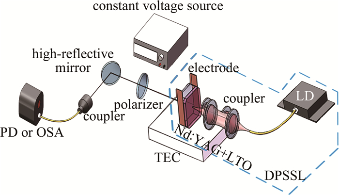
双频微片激光器的结构及对输出双频激光的测量方法如图 1所示。激光器谐振腔由掺杂原子数分数为0.01的Nd3+:YAG增益介质与电光晶体钽酸锂(li-thium tantalite,LTO)光胶而成,Nd3+:YAG和LTO晶体厚度分别为0.4mm和1.0mm,横截面积为5mm×5mm。在Nd:YAG端面镀有对1064nm的高反膜(R>99.7%)和对808nm的增透膜(T>97%),作为谐振腔的输入镜。LTO的端面镀有对1064nm的高反膜(R=99%),作为谐振腔的输出镜。半导体抽运固体激光器(diode pumped solid-state laser,DPSSL)尾纤输出中心波长为793nm的激光作为抽运源,与Nd3+离子的吸收峰相匹配。抽运光束通过一对耦合透镜聚焦到Nd:YAG晶体中,聚焦光斑直径约为100μm。利用LTO的双折射特性,可以分裂单纵模,产生具有垂直偏振特性的双频激光。半导体热电制冷器(thermoelectric cooler,TEC)用来控制微片激光器的温度,LTO的两个相对的侧表面镀有一层金膜,金膜与电极相连,通过外加电压,可以对LTO施加横向电场。双频微片激光器产生的双频光通过偏振片后可以产生拍频信号,经过对于1064nm波段的高反镜,分离输出激光和抽运光。后端利用光电探测器(photoelectric detector, PD)、频谱分析仪(optical spectrum analyzer, OSA)和波
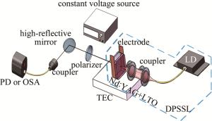
Figure 1. Schematic diagram of experimental setup
长计探测输出激光。
在谐振腔中,满足驻波条件能够稳定振荡的频率为:
$ {{v}_{q}}=q\frac{c}{2L} $
(1) 式中,c是真空中的光速,L是谐振腔光程,q是自然数,每一个q值对应一个纵模。相邻纵模间隔为c/(2L)。对于本次实验中研究的激光器谐振腔,其光程为:
$ L={{n}_{\text{YAG}}}\times {{l}_{\text{YAG}}}+{{n}_{\text{LTO}}}\times {{l}_{\text{LTO}}} $
(2) 式中,lYAG与lLTO分别表示Nd:YAG和LTO晶体的厚度;nYAG表示Nd:YAG的折射率为1.82,nLTO表示LTO的平均折射率为2.14,计算得到纵模间隔为52.3GHz。Nd:YAG的总增益带宽约为120GHz,这意味着谐振腔中最多可以产生两个纵模模式。在实验中通过使用相对较低的抽运功率(在阈值功率范围1.6倍以内),可以很容易地得到单纵模。
LTO晶体采用a轴切割,其自然双折射效应将单纵模分裂为垂直偏振的两个频率,分别为沿y轴方向偏振的寻常光和沿x轴方向偏振的非寻常光。二者的频差可由下式计算得到:
$ \Delta v=\frac{2{{l}_{\text{LTO}}}}{\lambda }\left( {{n}_{\text{e}}}-{{n}_{\text{o}}} \right)\frac{c}{2L} $
(3) 式中,ne和no是寻常光和非寻常光的折射率,其值分别为ne=2.1403,no=2.1363[17]。λ取近似值等于1064nm。LTO晶体的双折射率的变化与温度有关,双频频差受LTO的温度影响。(3)式等号两端分别对温度求导,并考虑热膨胀效应:
$ \frac{\text{d}\Delta v}{\text{d}T}=\frac{2{{l}_{\text{LTO}}}}{\lambda }\left[ \frac{\partial {{n}_{\text{e}}}}{\partial T}-\frac{\partial {{n}_{\text{o}}}}{\partial T}+\alpha \left( {{n}_{\text{e}}}-{{n}_{\text{o}}} \right) \right]\frac{c}{2L} $
(4) 式中,α为LTO沿z轴方向的热膨胀系数,α=16×10-6/℃。本文中取∂no/∂T=25×10-6/℃,∂ne/∂T=2.4×10-6/℃[17]。(4)式决定了频差与温度的变化关系。
LTO作为一种电光晶体,其双折射率也可以通过电场进行调谐。在实验中,沿x轴方向对LTO晶体施加横向电场。电光效应使LTO晶体沿x轴和y轴的折射率发生了变化,变化值与电场强度和LTO晶体的电光系数有关:
$ \left\{ \begin{align} & \Delta {{n}_{\text{o}}}=-\frac{{{\gamma }_{13}}n_{\text{o}}^{3}V}{2d} \\ & \Delta {{n}_{\text{e}}}=-\frac{{{\gamma }_{33}}n_{\text{e}}^{3}V}{2d} \\ \end{align} \right. $
(5) 式中,V为电压,电光系数γ13=8pm/V, γ33=33pm/V, d表示电极间距,即LTO沿x轴方向的宽度。将(5)式代入(3)式,双频频差与电压的关系为:
$ \frac{{{\rm{d}}\Delta v}}{{{\rm{d}}\mathit{V}}} = \frac{{{l_{{\rm{LTO}}}}}}{\lambda }\left[ {\frac{{{\gamma _{13}}n_{\rm{o}}^3 - {\gamma _{33}}n_{\rm{e}}^3}}{d}} \right]\frac{c}{{2L}} $
(6) (4) 式和(6)式给出了频差Δν与温度和电压的理论关系。计算出频差随温度和电压的变化率分别为:$\frac{\text{d}\Delta v}{\text{d}T}=2.36$GHz/℃, $\frac{\text{d}\Delta v}{\text{d}\mathit{V}}=2.56$MHz/V。
温度和电压可以调谐频差的原因在于温度和外加电场改变了钽酸锂晶体的折射率,这种折射率的变化与光波前相位特征没有关系。所以以上分析适用于所有相同条件下正交偏振光之间的频差调谐特性,包括x偏振方向(xp)TEM00和y偏振方向(yp)TEM00,以及y偏振方向(yp)TEM00和x偏振方向(xp)LG01。这有助于更好地预测实验结果。
-
抽运光从谐振腔的中心入射,保证晶体温度分布接近轴对称,用以产生拉盖尔-高斯模。在输出端放置布儒斯特棱镜,分离垂直偏振的两个光束。由于3个横模的竞争,双偏振态光束可以很容易产生。它们分别是x偏振方向(xp)的TEM00,y偏振方向(yp)的TEM00和x偏振方向的LG01。x方向和y方向偏振光的波长不同,而且x方向的偏振光的阈值比y方向低,所以观察到的LG01经常是沿x方向偏振。在抽运功率增加的过程中,抽运功率达到0.4W时,达到激光输出阈值,此时输出(xp)TEM00。当抽运功率达到1.1W,x方向偏振光中的LG01模开始起振。当抽运功率达到1.4W时,LG01模处于主导地位,LG01对TEM00的增益有抑制作用,由于模式竞争,(xp)TEM00变弱。随着抽运功率增加,(yp)TEM00逐渐到达输出阈值,它和(xp)TEM00也有竞争。因为(yp)TEM00的光频与(xp)LG01不同,所以二者的驻波在谐振腔中有相移。考虑到空间烧孔效应,(yp)TEM00和(xp)LG01之间的竞争强度弱于(xp)TEM00和LG01。所以2个TEM00的竞争中,(yp)TEM00能够抑制(xp)TEM00。最终抽运光功率在1.4W~1.7W之间时,激光器输出的双频分别为(xp)LG01和(yp)TEM00。
为了检验x偏振方向涡旋光的相前,在输出光路上放置布儒斯特棱镜,分离(xp)LG01和(yp)TEM00,其后搭建了Mach-Zehnder干涉系统。利用球面波和平面波分别与涡旋光产生干涉。产生干涉时主要考虑涡旋光的相位因子项,涡旋光的电场表达式为:
$ {E_1}{\rm{ = }}{A_1}\exp \left( {{\rm{i}}l\theta } \right) $
(7) 式中,l为拓扑荷数,θ为方位角。
简单起见,假设其振幅A1为固定值, 考虑其与平面波和球面波干涉。平面波和球面波的电场表达式为:
$ {E_2} = {A_2}\exp \left( {{\rm{i}}\frac{{2{\rm{ \mathsf{ π} }}\mathit{x}}}{\lambda }} \right) $
(8) $ {E_3} = {A_3}\exp \left[ {{\rm{ - i}}kz\left( {1 + \frac{1}{2}\frac{{{x^2}}}{{{z^2}}} + \frac{1}{2}\frac{{{y^2}}}{{{z^2}}}} \right)} \right] $
(9) 式中,波数k=2π/λ。
令A2=A1=A3=E0,E0表示简谐波的振幅。(7)式分别和(8)式、(9)式叠加后,干涉光的光强表达式如下:
$ I = E{E^*} - E_0^2\left[ {2 + 2\cos \left( {{\rm{i}}l\theta + {\rm{i}}2{\rm{ \mathsf{ π} }}\mathit{x/}\lambda } \right)} \right] $
(10) $ \begin{array}{l} \;\;\;\;\;\;\;\;\;\;\;\;\;\;\;\;\;\;\;\;\;I = E{E^*} = \\ 2E_0^2\left\{ {1 + \cos \left[ {{\rm{i}}l\theta - {\rm{i}}kz\left( {1 + \frac{1}{2}\frac{{{x^2}}}{{{z^2}}} + \frac{1}{2}\frac{{{y^2}}}{{{z^2}}}} \right)} \right]} \right\} \end{array} $
(11) 式中,E表示光电场,E*为其共轭复数。
由(10)式和(11)式可以仿真出涡旋光和平面波的干涉图形,当拓扑荷数l=1时,其干涉图形如图 2所示。在实验中用CCD对干涉条纹进行观测,如图 2a和图 2c所示,并与对应的理论仿真结果作对比(见图 2b和图 2d),表明产生的涡旋光的拓扑荷数l的绝对值等于1。
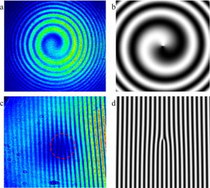
Figure 2. Experiment and simulation results of vortex beam interference fringes a—experimental interference fringe of LG01 and spherical wave b—simulation interference fringe of LG01 and spherical wave c—experimental interference fringe of LG01and plane wave d—simulation interference fringe of LG01 and plane wave
-
实验中可以通过聚焦经过偏振片的输出光束到光电探测器表面得到(xp)LG01和(yp)TEM00之间的拍频信号。但同时也发现, 当两者的频差下降至几个吉赫兹甚至更低的时候,(yp)TEM00会变得较弱,yp也不再是纯净的LG01,(xp)TEM00会起振。这是由于(xp)LG01和(yp)TEM00频率相近时,二者的驻波在谐振腔中相移减小,竞争变强,这与之前讨论的基于空间烧孔效应的竞争机制相吻合。(xp)TEM00与(xp)LG01会产生一个700MHz~800MHz之间的拍频信号,如图 3所示。而且这个拍频频率非常稳定,几乎不会随着LTO的温度和电压的变化产生漂移,它对(xp)LG01和(yp)TEM00之间拍频信号的调谐不产生影响。
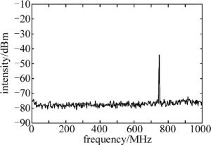
Figure 3. Beat signal between (xp)LG01 and (xp)TEM00
-
采用热光效应调谐双频的频差范围较大,能够达到纵模间隔的一半,即20GHz以上, 所以实验中首先使用波长计(最小分辨率0.01nm)对两个频率光波长进行比较粗糙的测量。实验中将微片激光器的温度控制在18℃~34℃,温度调谐间隔设为0.5℃。两个频率光波长的探测结果如图 4所示。
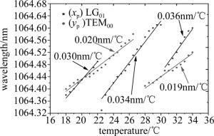
Figure 4. Wavelength of two transverse modes vs. temperature from 18℃ to 34℃
(xp)LG01和(yp)TEM00在图中分别对应☆和·数据点。对测量到的数据进行拟合,发现两个偏振方向上的光波长和温度近似为线性关系。从图中看出,对于(yp)TEM00,其波长随温度增加时在27℃出现大范围的变化;同样,对于(xp)LG01,在22℃和30℃时也出现了两次变化,这种现象是因为相邻两个的纵模发生了模式跳变。模式跳变的原因与增益谱线和输出光波长的相对位置有关。在一定抽运功率下,当有两个纵模的增益达到阈值,都有可能在谐振腔中形成振荡,并发生模式竞争。相对位置更靠近增益谱线中心的模式,将会获得更高的增益,在竞争中处于优势。处于劣势的模式就有可能得不到足够的增益而熄灭。实验中由于微片激光器的温度在变化,LTO晶体折射率也在变化,起振纵模模式的波长也会改变,本来处于增益谱线中心位置附近的模式,会逐渐漂移到边缘位置,增益减小;而本来处于增益谱线边缘没有达到阈值或超过阈值但增益很小的模式,会向中心位置靠近,增益变大。当后者的增益大于前者,在模式竞争中变为优势,就会使前者熄灭,后者取而代之。
另外,从图 4中也可以观察到,xp纵模每一次跳变后的起始波长都会有所增加,这是因为Nd:YAG的增益谱线的中心波长会随温度发生漂移[18-20]。这就导致在温度升高的过程中,发生模式跳变时,两个纵模的波长都比前一次模式跳变时更长。
双频激光器温度在18℃到22℃区间内时,两个垂直偏振光的波长随温度连续改变,均没有发生模式跳变。并且在20℃附近出现了频率交叠。为了更加精细的测量双频的频差,换用带宽为3.5GHz的光电探测器对该温度点附近的拍频信号的调谐进行探测,测量结果由射频频谱分析仪显示。该温度区间内频差与温度的关系曲线如图 5所示。
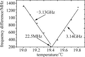
Figure 5. Frequency difference between (xp)LG01 mode and (yp)TEM00 mode around 0Hz vs. temperature
从图 5可以看出, 双频频差在19.4℃时出现折返,即达到了频差的最小值。从频谱仪中可以看到, 频差到达0Hz后折回的过程,但由于没有稳频装置,温控器温度恒定时,晶体温度也会产生微小的变动,导致在每一个温度点下的频差值也会有波动,大约为±50MHz,实验中取波动的中间值。在19.4℃时从频谱仪上得到频差值为22.5MHz。图 5中对频差折返前后随温度变化关系进行线性拟合,两段斜率基本一致,得到频差随温度的变化率为3.13GHz/℃和3.14GHz/℃。
-
为了能够更加精确地调节频差,对LTO晶体上的电极施加直流电压,产生的横向电场会改变LTO晶体b轴和c轴的折射率,实现频差的调谐。电压与频差之间的关系取决于(6)式。将频差控制在光电探测器带宽范围内,使温度保持19.4℃恒定,用高压直流源对LTO两侧的电极施加可调电压,该电压源最小输出值为500V。图 6中可以得到拍频随电压的变化关系。
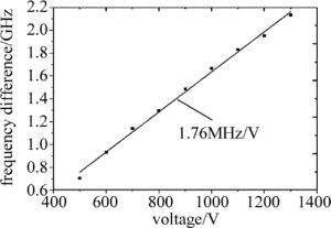
Figure 6. Frequency difference vs. voltage under voltage tuning condition
测量结果表明, 频差与电压成良好的线性关系,频差对电压的调谐灵敏度为1.76MHz/V。利用LTO晶体的电光效应,可以对频差进行快速的调谐。另外,在此基础上加入锁相环[21],将实际频差与目标频差的差值转换为电压值反馈回LTO晶体,可以实现稳频功能。再考虑到电压的控制精度为1V,这比利用热效应调谐频差更灵敏与准确。理论上,增大施加在LTO晶体上的电压,可以达到温度调谐时同等的频差值。然而由于频差对电压调谐灵敏度较小,利用电光效应大范围的调谐频差较为困难,如果想要达到20GHz的频差,大约需要施加12kV的高压,与温度调谐法相比,增加了系统的成本,也对晶体外壳的绝缘性提出更高的要求。所以,结合温度与电压两种调谐方法,可以容易的做到大范围、高精度的频差调谐。
-
本文中针对双偏振微片激光器输出的双横模模式拍频的可调谐性进行了深入理论与实验研究。首先利用LD抽运双偏振微片激光器,直接产生了具有波前螺旋性的模。双偏振谐振腔结构为模与拉盖尔-高斯模式具有不同的偏振方向和频率提供了前提。基于LTO晶体的电光效应和热光效应,对(xp)LG01和(yp)TEM00的频差进行调谐研究。通过理论分析,发现温度和电压可以在不同的尺度上调节频差。实验结果得到温度和电压对频差的调谐灵敏度分别为3.14GHz/℃和1.76MHz/V。采用温度和电压相结合的调谐方法,实现了频差的大范围和高精度调谐。
双横模输出微片谐振腔双频频差调谐特性研究
Study on dual-frequency difference tuning characteristics of microchip cavity with two transverse mode output
-
摘要: 双偏振激光谐振腔能够产生两个垂直偏振的横模模式, 分别为基横模(TEM00)和具有轨道角动量的涡旋光束(LG01), 二者在光频率上具有频差。为了研究两个横模的频率差调谐特性, 采用温度与电压相结合的调谐技术方法, 实现拍频信号在不同频率范围的连续调谐。理论计算分析了两模式频差分别与温度和电压的对应关系, 实验实现了频差的大范围可调谐性, 并对频差的调谐精度进行了测量分析。结果表明, 频差与温度和电压之间都呈现出良好的线性关系, 并得到对温度和电压的调谐斜率分别为3.14GHz/K和1.76MHz/V。该研究能够更好地分析双偏振谐振腔直接产生涡旋光束现象, 并在激光通信和激光雷达探测等技术领域具有应用价值。Abstract: Two perpendicularly polarized transverse mode modes can be generated by a bipolarized laser resonator, namely fundamental transverse mode (TEM00) and vortex beam with orbital angular momentum (LG01). There is frequency difference in optical frequency. In order to study frequency difference tuning characteristics of two transverse modes, tuning technique combining temperature and voltage was adopted. Continuous tuning of beat signal in different frequency ranges was realized. The relationship between frequency difference of two modes vs. temperature and voltage was analyzed theoretically. Experiments showed that frequency difference can be tuned in wide range. Tuning accuracy of frequency difference was measured and analyzed. The results show that, there is good linear relationship between frequency difference vs. temperature and voltage. The tuning slopes of temperature and voltage are 3.14GHz/K and 1.76MHz/V, respectively. This study can better analyze the phenomenon of vortex beam generated directly by dual polarization resonator. It has application value in the fields of laser communication and lidar detection.
-
Figure 2. Experiment and simulation results of vortex beam interference fringes a—experimental interference fringe of LG01 and spherical wave b—simulation interference fringe of LG01 and spherical wave c—experimental interference fringe of LG01and plane wave d—simulation interference fringe of LG01 and plane wave
Figure 5. Frequency difference between (xp)LG01 mode and (yp)TEM00 mode around 0Hz vs. temperature
-
[1] PILLET G, MORVEN L, MENAGER L, et al. Dual-frequency laser phase locked at 100GHz[J]. Journal of Lightwave Technology, 2014, 32(20): 3824-3830. doi: 10.1109/JLT.2014.2333036 [2] PAQUET R, BLIN S, MYARA M, et al. Coherent continuous-wave dual-frequency high-Q external-cavity semiconductor laser for GHz-THz applications[J]. Optics Letters, 2016, 41(16): 3751-3754. doi: 10.1364/OL.41.003751 [3] BRUNEL M, LAI N D, VALLET M, et al. Generation of tunable high-purity microwave and terahertz signals by two-frequency solid state lasers[J]. Proceedings of the SPIE, 2004, 5466:131-139. doi: 10.1117/12.554782 [4] MCKAY A, DAWES J M. Terahertz generation using a two-frequency highly-doped ceramic Nd: YAG microchip laser[C]// Conference on Lasers and Electro-Optics/International Quantum Electronics Confe-rence. Washington DC, USA: Optical Society of America, 2009: JTuD1. [5] WANG Y A, KE Y Zh, CUI S N, et al. Experimental study about power balance mechanism in dual-frequency microchip lasers[J]. Laser Technology, 2018, 42(5):651-654(in Chinese). [6] HU M, ZHANG Y, WEI M, et al. Microchip dual-frequency laser with well-balanced intensity utilizing temperature control[J]. Optics Express, 2016, 24(20): 23383-23389. doi: 10.1364/OE.24.023383 [7] LI J, NIU Y, NIU H. Frequency difference stabilization in dual-frequency laser by stress-induced birefringence closed-loop control[J]. Applied Optics, 2016, 55(16):4357-4361. doi: 10.1364/AO.55.004357 [8] ZHANG Z L, GUI K, ZHAO Ch M, et al. Self-Q-switch regime based on a beat effect with a dual-frequency microchip laser[J]. Physical Review, 2018, A98(3): 033831. [9] WANG B, WANG Y, KONG L, et al. Multi-target real-time ranging with chaotic laser radar[J]. Chinese Optics Letters, 2008, 6(11): 868-870. doi: 10.3788/COL20080611.0868 [10] ZHENG X Y, ZHAO CH M, ZHANG H Y, et al. Coherent dual-frequency lidar system design for distance and speed measurements[J]. Proceedings of the SPIE, 2018, 10619:106190S. [11] ONORI D, SCOTTI F, LAGHEZZA F, et al. Coherent laser radar with dual-frequency Doppler estimation and interferometric range detection[C]//2016 IEEE Radar Conference (Radar Conf). New York, USA: IEEE, 2016: 1-5. [12] CHEN J, ZHU H, XIA W, et al. Self-mixing birefringent dual-frequency laser Doppler velocimeter[J]. Optics Express, 2017, 25(2):560-572. doi: 10.1364/OE.25.000560 [13] LAVERY M P J, SPEIRITS F C, BARNETT S M, et al. Detection of a spinning object using light's orbital angular momentum[J]. Science, 2013, 341(6145):573-540. [14] KIM J W, CLARKSON W A. Selective generation of Laguerre-Gaussian (LG0n) mode output in a diode-laser pumped Nd:YAG laser[J]. Optics Communications, 2013, 296:109-112. doi: 10.1016/j.optcom.2013.01.046 [15] WANG Y, SHEN Y, MENG Y, et al. Generation of 1535nm pulsed vortex beam in a diode-pumped Er, Yb:glass microchip laser[J]. IEEE Photonics Technology Letters, 2018, 30(10):891-894. doi: 10.1109/LPT.2018.2822838 [16] KIM D J, KIM J W, MACKENZIE J I. Adaptable beam profiles from a dual-cavity Nd:YAG laser[J]. Optics Letters, 2016, 41(8):1740-1743. doi: 10.1364/OL.41.001740 [17] ROLLAND A, FREIN L, VALLET M, et al. 40GHz photonic synthesizer using a dual-polarization microlaser[J]. IEEE Photonics Technology Letters, 2010, 22(23):1738-1740. doi: 10.1109/LPT.2010.2084077 [18] ZHAO Sh Zh, CHEN L, ZHANG L, et al. Study on temperature dependence of the 1.064μm stimulated emission cross section of Nd:YAG crysyal[J]. Acta Photonica Sinica, 2004, 33(2):133-135(in Chinese). [19] WANG X B, XU X J, LU Q Sh. Effect of thermally induced change of stimulated emission cross section in heat capacity lasers[J]. Ch-inese Journal of Lasers, 2009, 36(1):43-46(in Chinese). doi: 10.3788/CJL20093601.0043 [20] SATO Y, TAIRA T. Comparative study on the temperature depen-dent emission cross section of Nd: YAG, Nd: YVO4, and Nd: GdVO4[C]//Frontiers in Optics. Washington D C, USA: Optical Society of America, 2011: FThB4. [21] ROLLAND A, LOAS G, BRUNEL M, et al. Non-linear optoelectronic phase-locked loop for stabilization of opto-millimeter waves: Towards a narrow linewidth tunable THz source[J]. Optics Express, 2011, 19(19):17944-17950. doi: 10.1364/OE.19.017944 -

 点击查看大图
图(6)
计量
- 文章访问数: 4791
- HTML全文浏览量: 2971
- PDF下载量: 23
- 被引次数: 0
