 网站地图
网站地图

 下载:
下载:


-
光学相干层析成像(optical coherence tomography, OCT)技术是20世纪90年代萌芽并迅速发展起来的一种新型的非接触、非侵入的无损3维成像技术。通过对样本内部反射光或散射光的测量,利用计算机可以重构出样本内部结构的2维图像或者3维图像。太赫兹(terahertz, THz)波是指频率从0.1THz~10THz的电磁波,在非极性材料中具有很强的穿透能力。2000年,JOHNSON等人[1]利用太赫兹辐射源作为OCT的弱相干光源,制造出了结合OCT技术和THz技术优势的太赫兹波相干层析系统,精确的3维成像为探测非极性材料的内部结构提供了实现的可能。
近年来,日趋成熟的OCT技术在医疗及科研等领域的应用越来越广泛[2-15],与此对应的相干层析成像系统的分辨率也越来越高。由光学干涉原理可知,辐射源的相干长度依赖于中心波长的平方和辐射源的谱宽,即与前者成正比,与后者成反比[16]。为了提高OCT系统的纵向分辨率,宽频光源逐渐进入了人们的视线。迄今为止,该系统已获得了微米量级的纵向分辨率。但是引入宽频光的同时引起了色散,尤其是在样品的色散系数较大时,色散问题更加不容忽视[17-20]。因此,搭建超高分辨率的OCT系统的核心技术之一就是色散补偿。
色散补偿方法主要有两种,即硬件补偿[21-25]和数值补偿[20, 26-30]。硬件补偿方法为了实现迈克尔逊干涉仪中参考臂和样品臂的色散匹配,需要在参考臂中添加一些用以补偿色散的器件[30-31]。额外硬件的引入增加了系统的成本和复杂度,而且样品的色散特性必须在添加补偿器件之前提前掌握;当改变样品或系统光路时还需要重新调整色散补偿器件,因此在实际应用中具有一定的局限性。数值补偿方法[26-28]正好可以避免这些缺点。其中,以迭代补偿算法为代表的数值补偿方法通过不断调用评价函数,使之达到极值,从而得到最佳补偿系数。
本文中通过搭建太赫兹OCT系统,从产生的干涉信号中分析色散产生的原因及影响,再利用迭代补偿算法进行色散补偿,从而得到高纵向精度(高于100μm)的3维重构图像。
-
实验中搭建的太赫兹相干层析成像系统的光路图和实物图如图 1所示。

Figure 1. Light path diagram of system
由图 1可知,成像系统主要由5个模块组成,包括用作光源的中压汞灯、由一个孔径光阑和两个离轴抛物镜(off-axis parabolic mirror, OAP)组成的校准模块、迈克尔逊干涉仪、由两个步进电机和一个控制器组成的扫描模块和由计算机、锁相放大器以及Tydex公司生产的Golay cell探测器组成的信号采集与处理模块。其中,中压汞灯的输出频率为(1~20)THz,半峰全宽为12THz,其对应的中心波长λ0=27.3μm、谱宽Δλ0=42.4μm;校准模块主要用于准直光源发出的太赫兹波并对光束的横向尺寸进行调整;在迈克尔逊干涉仪模块,核心部件是制作在Mylar薄膜上的分束器(beam splitter, BS),经准直后的THz波入射到分束镜上分成两束(参考光和探测光),参考光被金属反射镜M1反射回到原来的分束镜,探测光则被一抛物面镜进行聚焦,照射在载物台上样品后反射回来,与参考光发生干涉;扫描模块中,1维步进电机利用反射镜作1维纵向扫描,2维步进电机对样品作2维横向扫描;在信号采集与处理模块中,利用高莱探测器探测输出的干涉THz信号,再用锁相放大器将探测到的信号放大并输入到计算机,经过相应的数据处理后就可以显示重构出的3维样品图像。
-
在时域相干层析系统中,太赫兹波的谱密度函数G(ω)与自身的实相干函数G(τ)是一个傅里叶变换对[24],即:
$ G\left( \tau \right)\text{=}\left\langle E\left( t \right)\cdot E\left( t+\tau \right) \right\rangle =\int_{-\infty }^{\infty }{G\left( \omega \right){{\text{e}}^{\text{i}\omega \tau }}\text{d}\omega } $
(1) 式中,ω为角频率; τ为时延; t为时间变量;E(t)为太赫兹波的电场分量。
若在太赫兹波的频谱中引入与深度扫描路径相关的相位Φ0(Φ0=ωτ0,τ0为时延),并考虑色散的影响,(1)式可改写成:
$ \begin{align} & {{G}_{\text{disp}}}\left( \tau +{{\tau }_{0}} \right)=\left\langle E\left( t \right)\cdot E\left( t+\tau \right) \right\rangle \text{=} \\ & \text{ }\int_{-\infty }^{\infty }{G(\omega ){{\text{e}}^{-\text{i}({{\mathit{\Phi }}_{0}}+{{\mathit{\Phi }}_{\text{disp}}}}}){{\text{e}}^{\text{i}\omega \tau }}\text{d}\omega } \\ \end{align} $
(2) 式中,Φdisp为样品的色散相位。
由(2)式可知,Φdisp的引入导致时域的信号包络产生展宽,色散补偿正好可以抵消这种展宽。在时域相干层析系统中,由于未知样品的色散系数和厚度,因此可以从初始设定的评价函数出发,不断地循环调用评价函数,直到达到初始设定的阈值时便可得到最佳补偿结果。
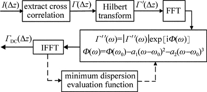
为了获得频域信号Γ″(ω),在所设计的时域相干层析系统中对原始干涉信号I(Δz)的自相关项Γ(Δz)进行希尔伯特变换(Hilbert transform, HT)和快速傅里叶变换(fast Fourier transform, FFT)。然后将Γ″(ω)的相位与已知的2阶和3阶色散做差,再利用快速傅里叶逆变换(inverse fast Fourier transform, IFFT)便可得到色散补偿后的干涉信号。在色散补偿过程中,色散评价函数的设计是核心。通过不断调整每次循环的2阶和3阶的色散补偿系数,可以使色散补偿达到最佳效果。所设计的时域相干层析系统中,迭代补偿算法的流程图如图 2所示。

Figure 2. Flow chart of iterative compensation algorithm
-
图 3是实验中所使用的两块厚度分别为200μm和230μm的低阻硅片,样品宽度均为50mm左右。横向扫描步长和纵向扫描步长分别为500μm(约为焦斑大小)和0.67μm。

Figure 3. Samples of imaging
图 4a和图 4b分别显示了太赫兹相干层析成像系统对厚度为200μm和230μm两片硅片进行纵向扫描后得到的干涉信号。从图中的干涉信号可以看出包含较多的噪声,这些噪声主要来自于探测器、电路、分束器和散斑等。为了更好地对有效信号进行色散补偿,在色散补偿之前需要对噪声进行滤波降噪处理。在实验中采用的滤波算法包括小波降噪和中值滤波[32]等,滤波后的结果如图 5所示。

Figure 4. Interference signals for the samples

Figure 5. Interference signal after filtering and denoising
将图 5的干涉信号与图 4所对应的干涉信号进行对比,发现原始图像中的噪声点得到了很大程度的抑制,图像对比度明显提高。将两片厚度不同的硅片滤波后的干涉信号利用上述迭代补偿算法分别进行色散补偿,结果如图 6所示。

Figure 6. 1-D depth signal after dispersion compensation
对比图 6与图 4可以看到, 经过迭代补偿算法进行色散补偿后,两片硅片样品的纵向干涉信号峰值宽度比原始信号明显变窄,效果理想。不过,由于原始信号中存在较多的噪声、较低的信噪比,使得补偿后的1维深度干涉信号与仿真得到的理想干涉信号之间仍然存在差距,但已经一定程度上提高了系统的深度分辨率,达到了不错的效果。由图 6a可知,干涉信号具有两个明显的峰值,分别位于光程长度180μm和890μm处,相应的硅片厚度为210.06μm;相似的,图 6b中的干涉信号也存在两个明显的峰值,分别在光程长度190μm和990μm处,硅片厚度为236.69μm。由此可知,测量得到的硅片厚度与两片样品的实际厚度相当吻合。
-
将图 3的两片低阻硅片并排放置在载物台上,利用太赫兹相干层析系统对原始数据进行重构可以得到如图 7a所示的3维图像。在3维成像过程中需要控制总成像时间和数据精度,导致纵向深度扫描中无法保证1维步进电机以稳定的速度移动,从而产生了扫描噪声。因此,在降噪滤波时必须同时考虑到探测器噪声、电路噪声、分束器噪声、散斑噪声和扫描噪声带来的影响。由于噪声频率通常比信号频率高,且干涉信号具有较低的信噪比,所以在滤波去噪过程中首先利用低通滤波器(截止频率比信号频率略高)滤去高频噪声,再采用小波变换和中值滤波进行降噪[30],处理后得到3维图像如图 7b所示。进一步利用迭代补偿算法对降噪滤波后的干涉信号进行色散补偿,结果如图 8所示。

Figure 7. 3-D reconstructed image of terahertz coherent tomography system

Figure 8. 3-D image after dispersion compensation
为了更好地观察和分析3维图像,可以画出如图 9所示的x-z方向剖面图。从图 9c可以明显地看出共有3层表面,分别位于z=55μm,z=260μm和z=290μm处。显然,最底层是载物台表面,其余的两层分别对应着两片低阻硅片的表面。通过实验可测得两片低阻硅片的厚度约为205μm和235μm,这与200μm和230μm的实际厚度也比较吻合。此外,由图中还可得到厚度差约为30μm的两片硅片所对应光程差约为100μm,因此,本实验中所搭建的太赫兹相干层析成像系统不仅能够获得所测样品的位置,还可获得100μm的纵向分辨率。

Figure 9. x-z direction profile corresponding to 3-D reconstruction image
-
本文中通过研究太赫兹相干层析成像系统中宽带光源对系统纵向分辨率的影响,提出色散补偿是实现高分辨率相干层析技术的关键之一。对成像系统的原始干涉信号进行降噪滤波后,利用迭代补偿算法对滤波后干涉信号进行色散补偿,并对比了原始干涉图像、滤波后干涉图像以及色散补偿后的干涉图像。研究发现能够获得纵向分辨率高达100μm的3维重构图像。此数值方法不需要预知被测样品的厚度和色散参量,因此在太赫兹无损探测领域具有较为广泛的应用。
基于太赫兹相干层析成像系统色散补偿的研究
Study on dispersion compensation based on terahertz coherent tomographic imaging system
-
摘要: 为了提高太赫兹相干层析成像系统的纵向分辨率,采用色散补偿方法解决了宽带光源做成像光源带来的色散问题。基于评价函数的迭代补偿算法对降噪滤波后的原始信号进行色散补偿,得到了较为清晰的3维重构图像。结果表明,在迭代补偿算法的计算中,无需预知样品的厚度信息以及色散特性,即可获得高精度的3维重构图像,纵向分辨率高达100μm。该研究在高精度的材料无损探测领域具有较大的研究价值和广泛的应用前景。Abstract: In order to improve the longitudinal resolution of a terahertz coherence tomographic imaging system, the dispersion compensation method was used to solve the dispersion problem caused by the broadband light source. The iterative compensation algorithm based on the evaluation function was used to compensate the dispersion of the original signal after noise reduction, and clear 3-D reconstructed images were obtained. The results show that 3-D high precision reconstruction images can be obtained without predicting the thickness information and dispersion characteristics of the sample. The longitudinal resolution is up to 100μm. This research has great research value and wide application prospect in the field of high precision nondestructive detection.
-
Figure 4. Interference signals for the samples
a—silicon wafer with a thickness of 200μm b—silicon wafer with a thickness of 230μm
Figure 5. Interference signal after filtering and denoising
a—silicon wafer with a thickness of 200μm b—silicon wafer with a thickness of 230μm
Figure 6. 1-D depth signal after dispersion compensation
a—silicon wafer with a thickness of 200μm b—silicon wafer with a thickness of 230μm
Figure 7. 3-D reconstructed image of terahertz coherent tomography system
a—original image b—image after filtering and denoising
-
[1] JOHNSON J L, DORNEY T D, MITTLEMAN D M. Background-free THz imaging using interferometric tomography[C]//Ultrafast Phenomena Ⅻ. Springer Series in Chemical Physics. Berlin, Heidelberg: Springer, 2001, 66: 262-264. [2] JI W, SUN Sh F, WANG S, et al. Analysis of noise model of optical coherence tomography image in logarithmic domain[J]. Laser Technology, 2014, 38(6): 848-853(in Chinese). [3] HU X Y, LIU L, LU Zh G. Application of optical coherence tomography[J]. Laser Technology, 1998, 22(6): 339-342(in Chinese). [4] TEARNEY G J, BREZINSKI M E, BOUMA B E, et al. In vivo endoscopic optical biopsy with optical coherence tomography[J]. Science, 1997, 276(5321): 2037-2039. doi: 10.1126/science.276.5321.2037 [5] YASUNO Y, ENDO T, MAKITA S, et al. Three-dimensional line-field Fourier domain optical coherence tomography for in vivo dermatological investigation[J]. Journal of Biomedical Optics, 2006, 11(1): 014014. doi: 10.1117/1.2166628 [6] ENDO T, YASUNO Y, MAKITA S, et al. Profilometry with line-field Fourier-domain interferometry[J]. Optics Express, 2005, 13(3): 695-701. doi: 10.1364/OPEX.13.000695 [7] BU P, WANG X Ch, OSAMI S. Fourier-domain optical coherence tomography based on sinusoidal phase modulation[J]. Acta Optica Sinica, 2007, 27(8): 1470-1474(in Chinese). [8] DUAN L, HE Y H, ZHU R, et al. Development of a spectrum domain 3-D optical coherence tomography system[J]. Chinese Journal of Lasers, 2009, 36(10): 2528-2533(in Chinese). doi: 10.3788/JCL [9] YANG L, WANG C, DING Zh H, et al. Image reconstruction in dioptric media for spectral domain optical coherence tomography[J]. Chinese Journal of Lasers, 2011, 38(5): 0504001(in Chinese). doi: 10.3788/CJL [10] WU T, DING Z, WANG K, et al. Swept source optical coherence tomography based on non-uniform discrete Fourier transform[J]. Chinese Optics Letters, 2009, 7(10): 941-944. doi: 10.3788/COL [11] QIN Y W. Study on optical coherence tomography detection of ZnO film[J]. Laser Technology, 2014, 38(6): 845-847(in Chinese). [12] SHI W, LI J Ch, HAN J, et al. Ball bearing measurement based on white-light interferometry technique[J]. Laser Technology, 2014, 38(5): 623-626(in Chinese). [13] CHEN Y P. Research of spectral-domain optical coherence tomography under white light irradiation[J]. Laser Technology, 2014, 38(3): 372-374(in Chinese). [14] QIN Y W. Study on micro-electromechanical system measurement using optical coherence tomography[J]. Laser Technology, 2013, 37(5): 664-667(in Chinese). [15] QIN Y W. Film thickness measurement based on optical coherence tomography[J]. Laser Technology, 2012, 36(5): 662-664(in Chinese). [16] MA B, SUI Q M, XU J. Design and application of new OCT scheme[J]. Microcomputer Information, 2008, 24(21):270-271(in Chinese). [17] HITZENBERGER C K, DREXLER W, BAUMGARTNER A, et al. Dispersion effects in partial coherence interferometry[J]. Proceedings of the SPIE, 1997, 2981:29-36. doi: 10.1117/12.274319 [18] HITZENBERGER C K, BAUMGARTNER A, FERCHER A. Dispersion induced multiple signal peak splitting in partial coherence interferometry[J]. Optics Communications, 1998, 154(4): 179-185. doi: 10.1016/S0030-4018(98)00280-6 [19] BAUMGARTNER A, HITZENBERGER C K, DREXLER W, et al. Resolution enhancement of partial coherence interferometry by dispersion compensation[J].Proceedings of the SPIE, 1997, 3192:162-170. doi: 10.1117/12.297837 [20] TUMLINSON A R, HOFER B, WINKLER A M, et al. Inherent homogenous media dispersion compensation in frequency domain optical coherence tomography by accurate k-sampling[J]. Applied Optics, 2008, 47(5): 687-693. doi: 10.1364/AO.47.000687 [21] GONG Q, JIANG J, WANG R K, et al. Dispersion compensation methods for ultrahigh-resolution optical coherence tomography[J]. Proceedings of the SPIE, 2006, 6047: 60471S. doi: 10.1117/12.710898 [22] DREXLER W, MORGNER U, GHANTA R K, et al. Ultrahigh-resolution ophthalmic optical coherence tomography[J]. Nature Medicine, 2001, 7(4): 502-507. doi: 10.1038/86589 [23] BOUMA B, TEARNEY G J, BOPPART S A, et al. High-resolution optical coherence tomographic imaging using a mode-locked Ti:Al2O3 laser source[J]. Optics Letters, 1995, 20(13):1486-1488. doi: 10.1364/OL.20.001486 [24] HITZENBERGER C K, BAUMGARTNER A, DREXLER W, et al. Dispersion effects in partial coherence interferometry: Implications for intraocular ranging[J]. Journal of Biomedical Optics, 1999, 4(1): 144-151. doi: 10.1117/1.429900 [25] CHEN Y, LI X. Dispersion management up to the third order for real-time optical coherence tomography involving a phase or frequency modulator[J]. Optics Express, 2004, 12(24): 5968-5978. doi: 10.1364/OPEX.12.005968 [26] FERCHER A F, HITZENBERGER C K, STICKER M, et al. Numerical dispersion compensation for partial coherence interferometry and optical coherence tomography[J]. Optics Express, 2001, 9(12): 610-615. doi: 10.1364/OE.9.000610 [27] TAO T, LIAO R, LV J. A new method to compensate dispersion in optical coherence tomography[J]. Optical Instruments, 2006, 28(5): 22-26(in Chinese). [28] MARKS D L, OLDENBURG A L, REYNOLDS J J, et al. Autofocus algorithm for dispersion correction in optical coherence tomography[J]. Applied Optics, 2003, 42(16): 3038-3046. doi: 10.1364/AO.42.003038 [29] TAO T. Dispersion effection in optical coherence tomography thoery[D]. Hangzhou: Zhejiang University, 2006: 62-66(in Chinese). [30] DREXLER W, MORGNER U, KÄRTNER F, et al. In vivo ultrahigh-resolution optical coherence tomography[J]. Optics Letters, 1999, 24(17): 1221-1223. doi: 10.1364/OL.24.001221 [31] BORN M, WOLF E. Principles of optics: electromagnetic theory of propagation, interference and diffraction of light[M]. 7th ed. Cambridge, UK: Cambridge University Press, 2000: 417-429. [32] HUANG Y X, YAO J Q, LING F R, et al. Terahertz imaging technology based on coherent tomography[J]. Laser & Infrared, 2015, 45(10): 1261-1265(in Chinese). -

 点击查看大图

图(9)
计量
- 文章访问数: 5664
- HTML全文浏览量: 3476
- PDF下载量: 149
- 被引次数: 0
