Advanced Search

ISSN1001-3806 CN51-1125/TN Map

Volume 44 Issue 5
Sep.  2020
Article Contents
Turn off MathJax

Citation:

Research of surface roughness measurement system based on laser scattering

  • Corresponding author: CHEN Peifeng, pfchen@mail.hust.edu.cn
  • Received Date: 2019-10-08
    Accepted Date: 2019-11-29
  • In order to measure the roughness parameters of metal and insulating surface, the oblique incidence roughness measurement system based on laser scattering was adopted. Using a semiconductor laser source, the scattering spot of roughness surface was photographed by complementary metal-oxide-semiconductor transistor industrial camera. The correspondence between the speckle characteristic parameters and roughness was then analyzed. According the theoretical and experimental study, the monotonic relation between the characteristic parameters and the roughness was verified. By using MATLAB to design graphical user interface, the function of one-key roughness measurement was realized. The results show that the system's structure is simple, and the error between the measurement result and stylus measurement result is less than 8% (the insulation surface is less than 5%), so the roughness of different materials can be measured. This result is helpful to the study of roughness measurement of object surface.
  • 加载中
  • [1]

    LIU B, FENG Q B, KUANG C F. Survey of measurement methods for surface roughness[J]. Optical Instruments, 2004, 26(5):54-58(in Chinese).
    [2]

    CHEN G, YE M. Analysis of measuring curved surface roughness method based on oblique laser scattering style[J]. Journal of Mecha-nical & Electrical Engineering, 2014, 31(12):1535-1540(in Chin-ese).
    [3]

    HAN X M. Ranking of XLPE insulation compounds in the manufacture of wire and cable[J]. Chemistry and Adhesion, 2008, 30(3):53-56(in Chinese).
    [4]

    HAN X H, DENG L M, WU B Y, et al. Process study on KDP crystal polished by picosecond laser[J]. Laser Technology, 2018, 42(2):166-171(in Chinese).
    [5]

    GITTENS R A, McLACHLAN T, OLIVARES-NAVARRETE R, et al.The effects of combined micron-/submicron-scale surface roughness and nanoscale features on cell proliferation and differentiation[J]. Biomaterials, 2011, 32(13):3395-3403. doi: 10.1016/j.biomaterials.2011.01.029
    [6]

    TIZIANI H J. Optical methods for precision measurements[J]. Optical and Quantum Electronics, 1989, 21(4):253-282. doi: 10.1007/BF02027299
    [7]

    SPAGNOLO G S, COZZELLA L, LECCESE F. Viability of an opto-electronic system for real time roughness measurement[J]. Measurement, 2014, 58:537-543. doi: 10.1016/j.measurement.2014.09.018
    [8]

    LIU Q Y, YU D J, WANG C T, et al. Development of the online measuring system of grinding surface roughness based on DSP[J]. Journal of Hunan University(Natural Sciences Edition), 2015, 42(8):1-7(in Chinese).
    [9]

    ZHU N N, ZHANG J. Multi-wavelength fiber sensor for measuring surface roughness based on laser scattering[J]. Infrared and Laser Engineering, 2016, 45(5):0522003(in Chinese). doi: 10.3788/irla201645.0522003
    [10]

    CHEN Ch, GUO X M, MA J, et al. Measurement of surface roughness based on laser angular-speckle correlation method[J]. Laser Technology, 2015, 39(4):497-500(in Chinese).
    [11]

    LU R S, TIAN G Y. On-line measurement of surface roughness by laser light scattering[J]. Measurement Science & Technology, 2006, 17(6):1496-1502.
    [12]

    WANG L Sh, YU L D. A research of the surface roughness measu-ring technique based on the laser scattering[J]. Advanced Display, 2011, 22(5):32-34(in Chinese).
    [13]

    YANG X M, WANG Y, ZHAO W L, et al. Research on the mea-surement system of large dimension workpieces based on the techno-logy of CCD and laser[J]. Applied Mechanics & Materials, 2010, 37/38:1101-1104.
    [14]

    GIGLIO M, MUSAZZI S, PERINI U. Surface roughness measurements by means of speckle wavelength decorrelation[J]. Optics Communications, 1979, 28(2):166-170. doi: 10.1016/0030-4018(79)90259-1
    [15]

    PATZELT S, STÖBENER D, STRÖBEL G, et al. Uncertainty of scattered light roughness measurements based on speckle correlation methods[J]. Proceedings of the SPIE, 2017, 10329: 103291P.
    [16]

    LEHMANN P. Surface-roughness measurement based on the intensity correlation function of scattered light under speckle-pattern illumination[J]. Applied Optics, 1999, 38(7):1144-1152. doi: 10.1364/AO.38.001144
    [17]

    RUFFING B. Application of speckle-correlation methods to surface-roughness measurement: A theoretical study[J]. Journal of the Optical Society of America, 1986, A3(8):1297-1304.
    [18]

    CHEN S T, ZHANG Y, HU H F. Surface roughness measurement based on fractal dimension of laser speckle[J]. Chinese Journal of Lasers, 2015, 42(4):0408002(in Chinese). doi: 10.3788/CJL201542.0408002
    [19]

    TCHVIALEVA L, MARKHVIDA I, ZENG H S, et al. Surface roughness measurement by speckle contrast under the illumination of light with arbitrary spectral profile[J]. Optics and Lasers in Engineering, 2010, 48(7/8):774-778.
    [20]

    SUN X B. Research on measurement technology of tubule inner surface roughness by laser scattering[D]. Harbin: Harbin Institute Technology, 2011: 1-59(in Chinese).
    [21]

    CHEN Sh Y, QI L H, CHEN B. Measurement and analysis of surface profiles by optical scattering method[J]. Infrared and Laser Engineering, 2006, 35(1):82-85(in Chinese).
    [22]

    ZENG Y, XU X, CHEN W R. A surface roughness measurement using laser scattering two dimensional features[J]. Laser & Infrared, 2008, 38(6):544-547(in Chinese).
    [23]

    ZHANG Q J, ZHAO Y H, HAN D, et al. On-line measurement of surface roughness based on laser two-dimensional scattering principle[J]. Opto-Electronic Engineering, 2011, 38(6):110-114(in Chin-ese).
  • 加载中
通讯作者: 陈斌, bchen63@163.com
  • 1. 

    沈阳化工大学材料科学与工程学院 沈阳 110142

  1. 本站搜索
  2. 百度学术搜索
  3. 万方数据库搜索
  4. CNKI搜索

Figures(7) / Tables(5)

Article views(7910) PDF downloads(22) Cited by()

Proportional views

Research of surface roughness measurement system based on laser scattering

    Corresponding author: CHEN Peifeng, pfchen@mail.hust.edu.cn
  • School of Optical and Electronic Information, Huazhong University of Science and Technology, Wuhan 430074, China

Abstract: In order to measure the roughness parameters of metal and insulating surface, the oblique incidence roughness measurement system based on laser scattering was adopted. Using a semiconductor laser source, the scattering spot of roughness surface was photographed by complementary metal-oxide-semiconductor transistor industrial camera. The correspondence between the speckle characteristic parameters and roughness was then analyzed. According the theoretical and experimental study, the monotonic relation between the characteristic parameters and the roughness was verified. By using MATLAB to design graphical user interface, the function of one-key roughness measurement was realized. The results show that the system's structure is simple, and the error between the measurement result and stylus measurement result is less than 8% (the insulation surface is less than 5%), so the roughness of different materials can be measured. This result is helpful to the study of roughness measurement of object surface.

引言
  • 表面粗糙度值是评价材料加工质量的一个重要参量,直接影响材料的使用性能和寿命[1]。金属材料在机械、电子、光学、医学等领域应用广泛,零件的表面微形貌很大程度上影响并决定了零部件的使用性能[2]。非金属材料在国家电力系统上应用广泛,例如交联聚乙烯(cross linked polyethylene, XLPE)绝缘材料[3],其表面粗糙度对电缆的电气性能有很大的影响,会影响到电缆的使用寿命[4]

    传统的接触式测量[5]容易对非金属绝缘表面造成划伤,测量速度低,测量电力系统时也会存在隐患,不适合在线测量[6]。采用非接触的测量[2]方法能够克服上述接触式测量的不足之处[7-10]。目前常用的非接触式粗糙度测量主要包括两大类:电子显微镜法和光学法。随着工业相机的发展,基于光散射的粗糙度测量系统得到广泛研究和应用[11-14]

    PATZELT等人利用互补金属氧化物半导体(complementary metal-oxide semiconductor, CMOS)相机拍摄物体表面反射光和散射光光强分布[15],经计算与分析其散斑光斑,对粗糙度测量的不确定度进行了分析估计,其研究结果为光散射法的测量精度提供了理论支持[16-17]。CHEN等人采用光散射法,利用电荷耦合器件(charge coupled device, CCD)相机拍摄散斑图像,计算散斑图像特征参量,通过特征参量与粗糙度之间的映射关系测得粗糙度[18-19]。LIU等人利用基于数字信号处理器(digital signal processor, DSP)的系统,用CCD相机拍摄散斑图,结合机器视觉和支持向量机技术,设计了一套粗糙度在线检测系统[8]。SUN基于光散射法,使用单片机控制硬件平台,实现了细杆内表面的粗糙度测量[20]

    本文中设计了一种基于激光散射的绝缘表面粗糙度测量系统,以CMOS工业相机为散射光斑的接收器,在MATLAB平台上调用相机获取散斑图并进行图像处理与计算,拟合相关特征参量与粗糙度值之间的关系,通过插值计算得到待测表面的粗糙度值。该测量系统光路简单, 无需嵌入式的硬件控制平台能实现快速的一键式测量,测量误差小于8%,用户界面操作简单,可编辑性强,适用于各种材料及加工表面的粗糙度测量。

1.   工作原理
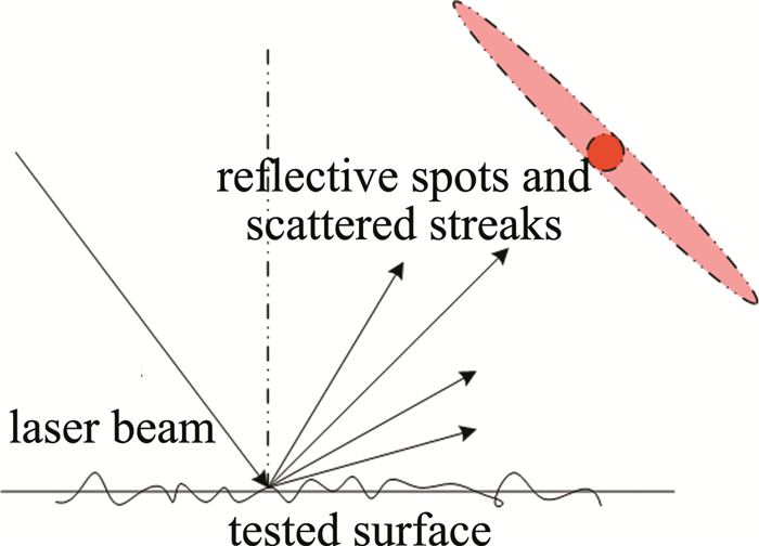
  • 当激光入射到金属表面时,光会发生反射和散射[21],散射光的空间分布的形状与表面粗糙度有关[12]。如图 1所示, 若材料表面比较光滑,则反射光斑较强,散射光带比较窄; 若表面比较粗糙,则反射光斑较弱,散射光带较宽[8]。因此散射光斑的离散程度也就能反映表面粗糙度值的特性。光斑的离散程度可用散射光特征值Sn表示[22-23]

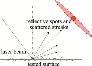
    Figure 1.  Schematic diagram of scattered light band on roughness surface

    式中, $P_{i}=I_{i} / \sum\limits_{i=1}^{n} I_{i}, \bar{l}=I_{i} / \sum\limits_{i=1}^{n} i P_{i} $, n为光电接收器阵列的光敏单元数,Ii为第i个单元的光电信号值,K为与系统有关的比例系数,i为对应像素位置序号。

    用工业相机拍摄散射光斑,得到离散化的散射灰度矩阵,通过建立数字图像的参量与粗糙度值之间关系得到拟合曲线,实现用散射特征值法间接测量物体表面的粗糙度。实际的图像处理中,利用灰度矩阵的均值E、标准差Sd、均方根(root mean square, RMS)RRMSR参量等表征光斑的光强信息和离散程度,定义为:

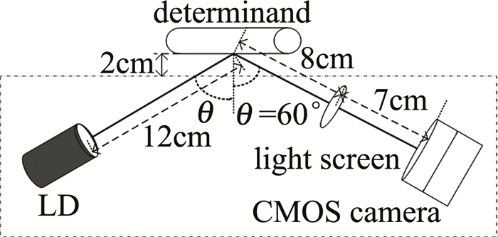
    与测量金属不同的是,当入射的激光照射在待测的塑料绝缘表面时,除了在表面的反射和散射光外,还会有另一部分光透射进材料里面被吸收和进行二次反射。当入射角过小,则透射的光能占绝大部分,散射光能过小,难以建立粗糙度值与光散射之间的关系。在本文中考虑到入射角度的影响,经过大量实验,选择入射角度为60°的斜入射测量结构能较好地建立粗糙度值与散射光斑参量之间的对应关系。

    图 2为测量系统的结构原理图。测量系统主要分为两个部分:光路部分和用户界面的数据处理及显示部分。

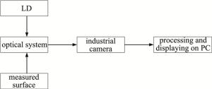
    Figure 2.  The frame diagram of test system

2.   系统设计
  • 本文中所采用光路结构如图 3所示。采用体积较小的半导体激光器作为光源,波长650nm, 功率5mW,半导体激光器输出光束经过扩束整形,出射的激光照射在被测物体表面,半径1cm的毛玻璃片作为光斑接收屏接收散射光斑,再利用MATLAB控制CMOS工业相机实时拍摄散射光斑。

    Figure 3.  Measurement structure of oblique incidence

  • 软件部分完成相机的调用及图形用户界面(graphical user interface,GUI)的制作和测量功能的实现,基于上述的光路结构,利用MATLAB调用相机并控制相机拍摄光斑图,对图像进行前期图像处理后,计算相关的参量拟合, 得到粗糙度值。设计的MATLAB的GUI界面如图 4所示。包括散斑图像的获取、显示、灰度化、滤波等功能和图像参量计算显示、粗糙度值的计算显示等功能。

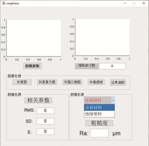
    Figure 4.  Functional structure of GUI

3.   验证试验
  • 对金属样品做验证性实验,找出与粗糙度值Ra之间存在单调性规律的散射光斑相关参量,并验证系统的可重复性与稳定性,为绝缘材料的测量提供实验数据的支撑,确定系统的可行性。实验中选择平磨和圆磨两种加工方式的标准粗糙度值的金属作为研究对象,其粗糙度值Ra分别为0.1μm,0.2μm,0.4μm,0.8μm,采集到的光斑图像如图 5所示。散射光斑可明显看出:随着粗糙度值的增大,散射光斑的整体光强度呈现减弱的规律。

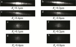
    Figure 5.  Scattering pattern of the measured sample

    计算光斑的相关参量,得到与Ra之间的对应关系,其中Ra为表面粗糙度最常用的一种表示方式,表示在取样长度内轮廓偏距绝对值的算术平均值,如表 1表 2所示。光斑的RRMS, SdE都呈现出与Ra的单调性关系。

    Ra/μm RRMS Sd E R1 R2
    0.1 77.25 66.5 39.31 0.86 1.694
    0.2 70.9 61.6 35.10 0.868 1.754
    0.4 45.36 40.12 21.16 0.866 1.73
    0.8 39.9 34.88 19.37 0.873 1.79

    Table 1.  Relationship between Ra and characteristic parameters of flat grinding metals samples

    Ra/μm RRMS Sd E R1 R2
    0.1 30.97 26.08 16.70 0.842 1.56
    0.2 24.54 20.58 13.37 0.837 1.53
    0.4 19.54 15.88 11.38 0.812 1.39
    0.8 12.65 9.5 8.35 0.75 1.14

    Table 2.  Relationship between Ra and characteristic parameters of external grinding metals samples

    对平磨的金属样品测量,改变系统的测量距离、测试点、相机曝光度,其中P1~P4为所做的4组对照实验,分析RRMS, SdE这3个参量与Ra的关系,结果分别如图 6所示。其中P1P2沿着竖直方向微量平移金属块,改变待测金属到分光镜之间的距离的测量结果, 可知在合适范围内微量改变测量的距离不会影响光斑参量与Ra之间的单调性关系; P2P3沿着水平方向移动待测金属,改变测量点的测量结果,可知参量曲线几乎重合,系统测量的可重复性较好; P3P4为改变相机曝光时间的测量结果,可知在合适范围内改变系统的曝光时间,各参量与Ra之间仍然保持单调性关系。验证了系统的稳定性及可重复性。

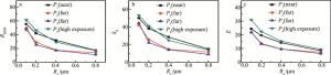
    Figure 6.  The relationship between the Ra and the parameters of scattering spot of flat grinding metal samples

    与上述实验步骤相同,将待测物换成绝缘塑料,如图 7所示。得到散射光斑的RRMSSdE都呈现出与Ra的单调性关系,验证了系统可用于测量绝缘表面。

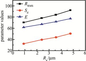
    Figure 7.  The relationship between Ra and scattering point parameters of insulating surface

  • 实际测量时,利用标准片定标得到参量与粗糙度值的拟合曲线,本文中是通过三次样条插值的方法得到拟合曲线。在保证实验条件不变的条件下,金属选择了平磨、外磨、刨床和平钳4种不同加工方式的样品,绝缘表面通过不同目数的砂纸机械化打磨了几组不同粗糙度值的样品,对两种材料的粗糙度值进行测量,在GUI界面的功能菜单中选定对应的测量目标,再点击“粗糙度”按钮,即能实现快速的测量功能。利用SdE两个参量分别拟合求得的粗糙度值如表 3表 4表 5所示。由测量结果可知, 利用这两个参量拟合求得的粗糙度值精度都较高,测量的4种金属相对误差在8%以内,测量的绝缘表面相对误差小于5%,能够实现金属和绝缘材料的粗糙度测量。

    samples Ra/μm flat-grinding metal external grinding metal
    0.1 0.2 0.4 0.8 0.1 0.2 0.4 0.8
    result and error/μm 0.107 0.213 0.428 0.797 0.106 0.198 0.416 0.814
    Ra-Sd/% 7 6.5 7 0.375 6 1 4 1.75
    result and error/μm 0.108 0.201 0.403 0.805 0.103 0.193 0.404 0.816
    Ra-E/% 8 0.5 0.75 0.625 2 3.5 1 2

    Table 3.  Roughness measurement results and errors of flat-grinding metal and external grinding metal samples

    samples Ra/μm planer metal flat pliers metal
    0.8 1.6 3.2 6.3 0.8 1.6 3.2 6.3
    result and error/μm 0.81 1.54 3.28 6.19 0.78 1.55 3.21 6.31
    Ra-Sd/% 1.25 3.75 0.625 1.746 2.5 3.1 0.33 0.16
    result and error/μm 0.79 1.57 3.17 6.32 0.80 1.58 3.19 6.29
    Ra-E/% 0.125 1.875 0.9375 1.27 0 1.25 0.33 0.16

    Table 4.  Roughness measurement results and errors of planer metal and flat pliers metal samples

    samples Ra/μm 4.76 3.56 2.37 1.22
    result and error/μm 4.85 3.67 2.43 1.14
    Ra-Sd/% 1.89 3.09 2.53 6.5
    result and error/μm 4.95 3.52 2.44 1.21
    Ra-E/% 3.99 1.12 2.95 0.82

    Table 5.  Roughness measurement results and errors of insulating surface

4.   结论
  • 非接触式的光学测量法对表面形貌的测量具有十分重要的研究意义,本文中设计出一套结构简单、使用方便的非接触式粗糙度测量系统,通过理论分析,确定了测量系统的可行性以及可重复性,经实验测量金属和绝缘表面的粗糙度值,验证了测量系统相对误差小于8%,其中对于粗糙度值较小的平磨和外磨金属的测量精度绝对误差小于0.03μm,粗糙度值较大的刨床和平钳加工金属测量绝对误差小于0.1μm,绝缘表面的测量精度绝对误差小于0.3μm。该系统精度较高、稳定性好,可重复性高,为其它材料的测量提供了思路,在非接触式在线测量与表面形貌分析等领域有很大的发展潜力。

Reference (23)

Catalog

    /

    DownLoad:  Full-Size Img  PowerPoint
    Return
    Return