Advanced Search

ISSN1001-3806 CN51-1125/TN Map

Volume 44 Issue 4
Jul.  2020
Article Contents
Turn off MathJax

Citation:

Research on laser scanning path planning method for UAV mountain environment

  • Received Date: 2019-08-30
    Accepted Date: 2019-09-24
  • Point cloud data of mountain power corridor space can be used to assist in path planning, reduce the probability of the drone flight accidents and effectively improve the efficiency and accuracy of the inspection with drones. In the process of path planning, the effectiveness of flight measurement and flight efficiency need to be taken into account. However, there is no effective way to solve this problem. In order to improve the effectiveness of flight measurement and flight efficiency, a path planning method combining sensor measurement characteristics was proposed, which was based on the maximum distance and angle of laser measurement, with flight efficiency and inspection target position as the constraints. The trajectory of flight was obtained by solving the planning equation, so as to ensure the safety and efficiency of the drone mountain environmental inspection. The experimental results show that the planning optimization effect is 7.58%, 11.18% and 13.33%, respectively, with consideration of the maximum measured distance d and measuring angle θ evaluated by the combined laser sensor of Velodyne VLP-16, RS-LiDAR-16 and HDL-32E. Therefore, the validity and correctness of the path planning method of laser scanning in mountain areas were verified.
  • 加载中
  • [1]

    CHEN Y, ZHOU B Zh, TAN J, et al. Research and application of airborne doppler wind lidars[J].Laser Technology, 2011, 35(6):795-799(in Chinese).
    [2]

    BLANCHARD S, KEARNEY B. Application of IRIDIUM(R) system technology to UAV based PCS services to the warfighter[C]//IEEE Military Communications Conference Proceedings MILCOM 1998.New York, USA: IEEE, 1998: 726936.
    [3]

    RAGO C, PRASANTH R, MEHRA R K, et al. Failure detection and identification and fault tolerant control using the IMM-KF with applications to the Eagle-Eye UAV[C]//Proceeding of the 37th IEEE Conference on Decision and Control. New York, USA: IEEE, 1998: 761963.
    [4]

    SMILJIAKOVIC V, GOLUBICIC Z T, MANOJLOVIC P S, et al. Application of integrated autonomous microwave position finding system and GPS for UAV navigation[C]//6th International Conference on Telecommunications in Modern Satellite, Cable and Broadcasting Service 2003.New York, USA: IEEE, 2003: 124627.
    [5]

    MITRA A K. Position-adaptive UAV radar for low-alfitude sensing applications[C]//2003 IEEE Aerospace Conference Proceedings.New York, USA: IEEE, 2003: 1235471.
    [6]

    PARK J K, AMRITA D, PARK J H. Application of agricultural subsidy inspection using UAV image[C]//Remote Sensing for Agriculture, Ecosystems, and Hydrology, Ⅹ Ⅷ.New York, USA: IEEE, 2016: 2241324.
    [7]

    ALIREZA A, PAYAM A, KANG K, et al. Neural adaptive observer-based sensor and actuator fault detection in nonlinear systems: Application in UAV[J]. ISA Transactions, 2016, 67:317-329.
    [8]

    CARNDUFF S, COOKE A. Application of aerodynamic model structure determination to UAV data[J]. The Aeronautical Journal, 2011, 115(1170): 481-492. doi: 10.1017/S0001924000006126
    [9]

    NAIDOO Y, STOPFORTH R, BRIGHT G. Development of an UAV for search & rescue applications[C]//IEEE Africon'11.New York, USA: IEEE, 2011: 6072032.
    [10]

    WANG Y H. Agriculture robot and applications[C]//Proceedings of the 2014 International Conference on Future Information Engineering and Manufacturing Science (FIEMS 2014). Beijing: International Research Association of Information and Computer Science, 2014: 35-57(in Chinese).
    [11]

    CLAUDIA S, ANETTE E, PIERRE K. Measuring gullies by synergetic application of UAV and close range photogrammetry[J]. Catena, 2015, 132:76-82.
    [12]

    BESADA J A, BERGESIO L, CAMPAÑA I, et al. Drone mission definition and implementation for automated infrastructure inspection using airborne sensors[J]. Sensors, 2018, 18(4): 43-54.
    [13]

    LIU Ch A, YAN X H, LIU Ch Y, et al. Dynamic path planning method for mobile robot based on improved ant colony algorithm[J]. Electronic Journal, 2011, 39(5):1220-1224(in Chinese). doi: 10.1109/INM.2011.5990675
    [14]

    SUN Sh Q, MA J. History and reality: The development process, present situation and challenges of UAV[J]. Cruise Missile, 2005 (1): 14-19(in Chinese).
    [15]

    CHUN Y, JIANG M, ZHANG H. Development status and prospect of UAV[J]. Cruise Missiles, 2005(2): 23-27(in Chinese).
    [16]

    ZHOU X M, ZHAO L B, ZHANG X L. Discussion on image processing technology and method of low altitude UAV[J]. Surveying and Mapping and Spatial Geographic Information, 2012, 35(2): 182-184(in Chinese).
    [17]

    WANG Zh H, HUANG X N, LIANG K, et al. Research on transmission line inspection system based on four-rotor UAV[J]. China Electric Power, 2012, 45(10): 59-62(in Chinese).
    [18]

    LIU Ch G, WANG X P, LIU Ch Y, et al. Three-dimensional track planning of UAV based on improved gray wolf optimization algorithm[J]. Journal of Huazhong University of Science and Technology (Natural Science Edition), 2017, 45(10): 38-42(in Chinese).
    [19]

    YAO S H. Development status and trend of UAV[J]. Electronic Fabrication, 2018(1):96-98 (in Chinese).
    [20]

    QI Sh J, JING L, WANG Y L. Summary of UAV system and its development trend[J]. Air Missile, 2018(4): 17-21 (in Chinese).
    [21]

    HU Zh H. Research on some key technologies of UAV track planning based on intelligent optimization algorithm[D]. Nanjing: Nanjing University of Aeronautics and Astronautics, 2011: 17-23(in Chin-ese).
    [22]

    BA H T. Research on UAV track planning[D]. Xi'an: Northwest University of Technology, 2006: 32-54 (in Chinese).
    [23]

    YANG G T, SU R Q, WU H, et al. Power tower inspection path planning of flying robot[J]. Journal of Huazhong University of Science and Technology (Natural Science Edition), 2015, 43(s1): 324-327(in Chinese).
    [24]

    JIA G Zh. Research on 3-D track planning of UAV based on genetic algorithm and sparse A* algorithm[D]. Nanjing: Nanjing University of Posts and Telecommunications, 2017: 55-67(in Chinese).
    [25]

    LIU Q W, LI Sh M, LI Z Y, et al. Research progress on forestry application of UAV lidar and photogrammetry[J]. Forestry Science, 2017, 53(7): 134-148(in Chinese).
  • 加载中
通讯作者: 陈斌, bchen63@163.com
  • 1. 

    沈阳化工大学材料科学与工程学院 沈阳 110142

  1. 本站搜索
  2. 百度学术搜索
  3. 万方数据库搜索
  4. CNKI搜索

Figures(11) / Tables(1)

Article views(6389) PDF downloads(27) Cited by()

Proportional views

Research on laser scanning path planning method for UAV mountain environment

  • 1. Production Technology Department, Guizhou Power Grid Co. Ltd., Guiyang 550002, China
  • 2. Transmission Operation and Maintenance Branch, Guizhou Power Grid Co. Ltd., Guiyang 550002, China

Abstract: Point cloud data of mountain power corridor space can be used to assist in path planning, reduce the probability of the drone flight accidents and effectively improve the efficiency and accuracy of the inspection with drones. In the process of path planning, the effectiveness of flight measurement and flight efficiency need to be taken into account. However, there is no effective way to solve this problem. In order to improve the effectiveness of flight measurement and flight efficiency, a path planning method combining sensor measurement characteristics was proposed, which was based on the maximum distance and angle of laser measurement, with flight efficiency and inspection target position as the constraints. The trajectory of flight was obtained by solving the planning equation, so as to ensure the safety and efficiency of the drone mountain environmental inspection. The experimental results show that the planning optimization effect is 7.58%, 11.18% and 13.33%, respectively, with consideration of the maximum measured distance d and measuring angle θ evaluated by the combined laser sensor of Velodyne VLP-16, RS-LiDAR-16 and HDL-32E. Therefore, the validity and correctness of the path planning method of laser scanning in mountain areas were verified.

引言
  • 平原地区地势平坦,各个杆塔海拔高度相近,可以设置一等高面进行2维路径规划。而山区环境地势起伏不定,各个杆塔处于不同海拔高度,无人机巡检路径应为3维路线, 故山区环境下需要进行无人机3维路径规划。无人机搭载激光传感器扫描获得山区电力走廊空间点云数据。在点云数据中进行快速路径规划,可以保证无人机山区环境巡检的安全性与准确有效性。

    本文中主要研究内容为基于山区环境的无人机激光扫描路径规划。研究无人机机载激光传感器的特性,分析激光传感器性能参量(包括测量角度θ、最大测量距离d等),针对传感器特性抽象其测量模型。通过输入杆塔坐标,结合激光传感器特性,规划生成最优路径,有效提升飞行效率。

1.   国内外现状
  • 随着微机电技术等相关技术的发展,无人机成本显著降低。20世纪80年代以来,计算机技术不断成熟,无人机应用在西方国家开始普及,例如无人机机载雷达应用[1]、无人机托管通信[2]、无人机容错控制[3]、无人机导航[4]、无人机位置自适应调整[5]、无人机检测[6]、无人机系统故障自检[7]、无人机系统识别[8]、无人机搜索救援应用[9]等。根据欧洲无人机研究预测,在未来30年内, 无人机市场将在农业、能源、公共安全/保安、电子商务/交付、移动和运输等领域迅猛发展。例如,在参考文献[10]中,提出在室外农田运用无人机(unmanned aerial vehicle, UAV),安装各种传感器实现自动采集和处理不同的信号。在参考文献[11]中,介绍了无人机近景摄影的运用以及图像的处理。在参考文献[12]中,重点研究利用多旋翼无人机进行基础设施检测的问题。

    无人机路径规划问题是无人机系统的重要研究应用,目标是根据设定的性能指标,比如航迹代价最小原则,即在规划空间中搜索出一条符合性能指标的最优路径。20世纪80年代以来,我国对无人机路径规划开展深入研究,如今在无人机动态路径规划[13]、无人机技术标准与法律障碍[14]、无人机发展趋势[15]、无人机测绘应用[16]、无人机输电线路巡检应用[17]、无人机3维航迹规划研究[18]、无人机军事与民用领域应用[19]、无人机系统研究[20]等领域取得一定突破。南京航空航天大学的HU博士对无人机静态航迹规划、突发威胁下航迹规划、无人机多机协同航迹规划及航迹平滑等关键技术做了较深入的研究[21]。西北工业大学的BA博士对航空数字地图及在线实时路径规划算法,在线突然威胁回避等领域进行了研究探索[22]。华北电力大学的YANG教授对有障碍物的2维简单环境、3维复杂环境两种情况下的电力杆塔巡检规划问题进行了深入探讨[23]。随着任务复杂度不断增加,我国路径规划技术向智能化的、可实时在线优化的方向发展,进一步缩小与国外先进水平的差距。
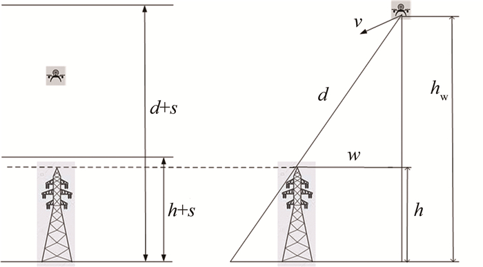
2.   飞行环境的空间约束模型
  • 图 1所示,设置杆塔塔高为h,无人机飞行高度hw,传感器测量最大测量距离为d,安全冗余距离为s,传感器与地面距离dw,无人机与杆塔连线水平面上垂直距离为w。为保证无人机飞行安全与测量有效性,应该满足以下约束条件:

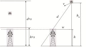
    Figure 1.  Constraint space

    飞行约束空间并不是静态的,而是随着无人机与山区环境的相对高度而变化。飞行约束环境核心是求取出无人机在此位置下与山区环境地面的相对高度,进而利用上述公式求取飞行约束环境。为了保证无人机飞行轨迹稳定,本文中设置多旋翼无人机飞行相对高度稳定为hw

    约束空间建模核心在于使无人机激光扫描区域与杆塔检测区域相重合,需要考虑测量距离、飞行高度、横向距离等因素,构建优化约束条件如前面所示。其中测量地面目标最大距离dw限定小于传感器测量最大有效距离d,保证激光扫描能够收集到地面信息。无人机相对飞行高度hw保持定值,避免无人机飞行过低撞上杆塔的情况。无人机横向距离w小于当前飞行高度对应的最大横向距离,限制无人机飞行的偏移量以优化路径航程大小。

3.   无人机山区环境激光扫描路径规划
  • 激光传感器的测量角度范围、测量距离、激光波长等参量的不同,无人机搭载激光传感器的测量范围与效果也不同[24],存在一个有效测量区间。进行无人机激光扫描路径规划,需要保证激光传感器有效测量区间与电力走廊空间相重合。因此,本文中研究激光传感器最大测量距离d与测量角度θ等特性,定义无人机与垂直距离w、无人机测量杆塔的最大距离R作为规划路径限制指标(如图 2所示)。

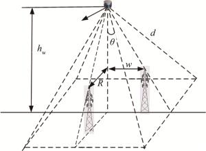
    Figure 2.  Effective measurement interval of the laser sensor

    传感器最大测量距离d限制无人机与杆塔的垂直距离w的范围。本文中设置(Sx, Sy), (Gx, Gy), (Nx, Ny)分别为两个杆塔和无人机的xy轴坐标。如图 3所示,首先求取无人机与两个杆塔之间的水平面上的距离l1, l2,以及两个杆塔之间的距离l3。利用3个边的关系可以求得无人机与两个杆塔连线的垂直距离w

    Figure 3.  Horizontal distance

    传感器测量角度θ与最大测量距离d限制无人机测量杆塔的最大距离R的大小,如图 4所示。设置无人机飞行高度为hw、无人机测量杆塔的最大距离R与传感器测量角度θ、最大测量距离d关系如下:

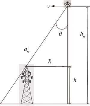
    Figure 4.  Maximum distance

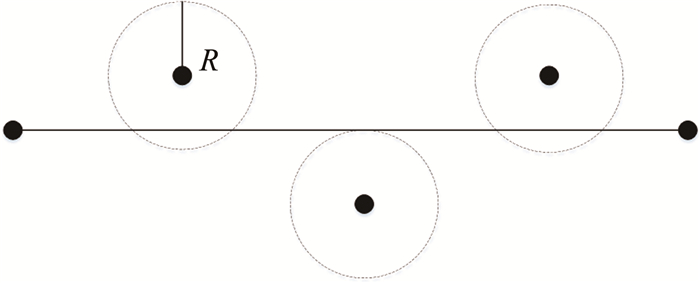
    将无人机测量杆塔的最大距离R作为电线杆塔吸引域的半径,无人机到达吸引域中任意一点均可保证杆塔检测有效性,如图 5所示。

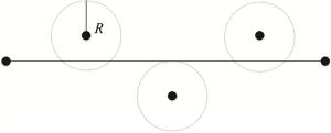
    Figure 5.  Attraction domain of pole tower

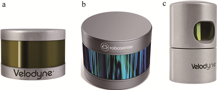
    本文中研究Velodyne VLP-16, RS-LiDAR-16, HDL-32E 3种激光传感器的特性,进行路径规划。激光传感器如图 6所示, 相关参量如表 1所示。

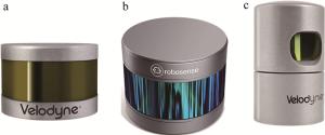
    Figure 6.  Three kinds of laser sensors

    model d/m θ
    Velodyne VLP-16 100 ±15°, vertical
    RS-LiDAR-16 150 ±15°, vertical
    HDL-32E 100 +10°~-30°, vertical

    Table 1.  Laser sensor parameters

  • 无人机路径规划需要考虑无人机的飞行航程问题。为保证无人机安全执行巡检任务,无人机需要在一定时间内完成任务并返航。定义最大航程lmax,进行无人机路径规划时计算前往下一个目标点并开始返航的航程是否超限。如果超限,规划无人机从此刻目标点立即返航,否则继续规划前往下一个目标点[25]。规划轨迹li与最大航程关系如下所示:

    式中,(xi, yi, zi)为当前无人机位置坐标,(xs, ys, zs)为无人机路径规划起始点。

  • 路径代价函数是无人机路径规划的重要评价指标,作用是保证无人机飞行的高效性与安全性。无人机飞行路径代价与航迹长度、终点距离两个因素相关联。进行无人机路径规划,既要考虑航迹长度大小,也要考虑与终点距离因素。

    设置第i段无人机飞行路径代价函数如下所示:

    式中,∑li表示从起始点到第i个位置点的所有轨迹段长度之和;lgoal表示第i个位置点到终点的距离;k为权重系数,在(0, 1)范围内。

  • 结合激光传感器特性,使用DIJKSTRA算法与人工势场法混合算法进行路径规划。DIJKSTRA算法进行全局规划,从起始点出发,逐步生成下一个转移点直至终点,保证路径经过所有杆塔目标点。同时使用人工势场法进行局部优化,计算杆塔对无人机的引力作用调整规划路径。规划流程如下所示:(1)加载杆塔目标点位置与环境信息,对山区环境离散化;(2)使用DIJKSTRA算法进行全局路径规划,综合考虑代价函数最小原则以及无人机与杆塔的垂直距离w的限制;(3)使用人工势场法按杆塔先后顺序进行局部优化,计算杆塔吸引域内吸引力最小的点作为新的目标点;(4)再次使用DIJKSTRA算法进行全局路径规划,更新规划路径;(5)判断是否优化完所有杆塔目标点,若未完成则返回第(2)步;(6)输出最优规划路径。

4.   实验验证
  • 在MATLAB平台上进行实验,验证结合传感器测量特性的路径规划方法的有效性与正确性。将实验分为无人机不结合传感器测量特性的路径规划、无人机结合Velodyne VLP-16激光传感器特性的路径规划、无人机结合RS-LiDAR-16激光传感器特性的路径规划、无人机结合HDL-32E激光传感器特性的路径规划4种情况,实验硬件条件为:Intel i5-7200U CPU与4.00GB RAM。

    无人机不结合传感器测量特性进行路径规划,规划路径总长度lall=570.9212m,规划路径如图 7所示。

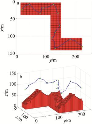
    Figure 7.  Planned path without sensor

    Velodyne VLP-16激光传感器最大测量距离d=100m,最大测量角度θ=15°, 规划路径总长度lall=527.6188m,规划路径如图 8所示。

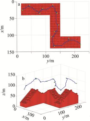
    Figure 8.  Planned path with Velodyne VLP-16 sensor

    RS-LiDAR-16激光传感器最大测量距离d=150m,最大测量角度θ=15°, 规划路径总长度lall=507.0738m,规划路径如图 9所示。

    Figure 9.  Planned path with RS-LiDAR-16 sensor

    HDL-32E激光传感器最大测量距离d=100m,最大测量角度θ=30°, 规划路径总长度lall=494.8212m,规划路径如图 10所示。

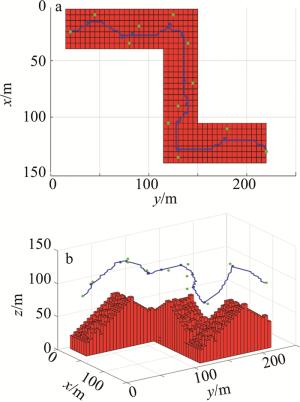
    Figure 10.  Planned path with HDL-32E sensor
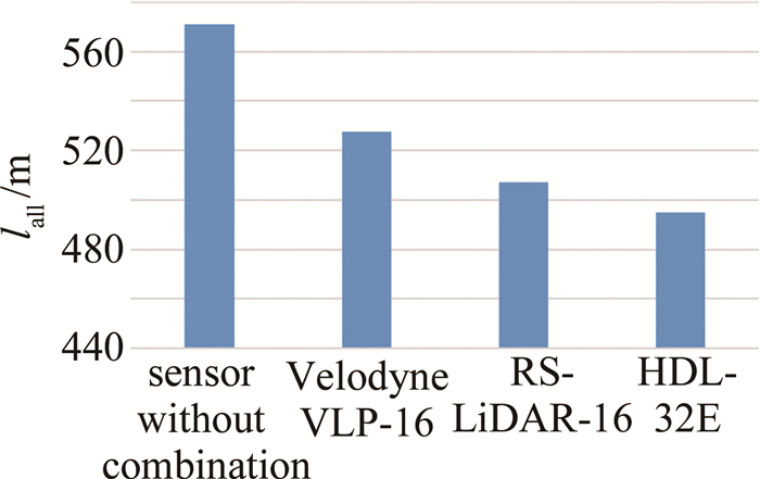
    4种情况实验结果如图 11所示。

    Figure 11.  Results of the experiment

    由此可知,与未结合传感器特性的规划路径长度相比较,结合Velodyne VLP-16激光传感器测量特性的规划路径长度减少优化了7.58%;结合RS-LiDAR-16激光传感器测量特性的规划路径优化长度减少了11.18%;结合HDL-32E激光传感器测量特性的规划路径优化长度减少了13.33%;验证了山区激光扫描路径规划方法的有效性和正确性。

5.   结论
  • 实现了一种结合传感器测量特性的路径规划方法。由实验验证可得:结合Velodyne VLP-16, RS-LiDAR-16, HDL-32E 3种激光传感器的最大测量距离d以及测量角度θ等特性进行路径规划,规划优化效果分别达到了7.58%, 11.18%, 13.33%。在山区环境中,根据杆塔之间竖直方向的相对位置关系,结合传感器测量特性,对杆塔目标点的高度改变Δh,规划路径的长度发生明显变化。因此,为了进一步提高规划优化效果,后续可加入杆塔目标点高度变化Δh的影响,将杆塔吸引域优化为3维球状吸引域,从而对杆塔目标点进行3维空间内的位置优化,进一步缩短规划路径长度,提高飞行的效率。

Reference (25)

Catalog

    /

    DownLoad:  Full-Size Img  PowerPoint
    Return
    Return