Advanced Search

ISSN1001-3806 CN51-1125/TN Map

Volume 44 Issue 1
Feb.  2020
Article Contents
Turn off MathJax

Citation:

Numerical simulation of flow field and thermal field with variable struction in reactive ion etching cavity

  • Corresponding author: FAN Bin, fanbin@ioe.ac.cn
  • Received Date: 2019-03-15
    Accepted Date: 2019-04-11
  • In order to improve the uniformity of etching, continuous fluid model and heat transfer model of gas flow were established for 400mm reactive ion etching(RIE) chamber. Pressure, velocity and temperature distribution in the reaction chamber were studied. When cooling plate was kept at 285K, the distributions of velocity, pressure and temperature near the wafer in the cavity were analyzed by changing the inlet flow rate and outlet pressure in turn. Then the distance between the plates (30mm~60mm), the diameter of the intake port (300mm~620mm) and the diameter of the exhaust port (50mm~250mm) were changed in turn. Air flow and temperature distribution in the reaction chamber were analyzed. The results show that, the distribution of air pressure is characterized by low edge and high center. The flow velocity is characterized by high edge and low center. The uniformity of air pressure is better at low flow rate. The uniformity of pressure distribution increases with the increase of the distance between the chamber plates. It also increases with the decrease of the outlet area and the increase of the inlet area of the chamber gas. The temperature field near the top of the wafer is uniform and stable. It is almost unaffected by the fluctuation of inlet flow. Thermal stability is good. The research results are of great significance to the structural design improvement of large-aperture RIE chamber and the control of large-aperture reactive ion etching process.
  • 加载中
  • [1]

    YAN H, YANG Ch L, SHI Q K, et al. Error in stitching testing for large aperture continuous phase plate[J]. High Power Laser and Particle Beams, 2013, 25(12):3329-3332(in Chinese). doi: 10.3788/HPLPB20132512.3329
    [2]

    YE Sh W, YANG P, WANG Zh Zh, et al. Error in stitching testing for large aperture continuous phase plate[J]. High Power Laser and Particle Beams, 2015, 27(6):064101(in Chinese). doi: 10.3788/HPLPB20152706.64101
    [3]

    CHEN H P, XIONG Zh, CAO T F, et al. Research on surface measure device for process of large aperture mirror assembly[J]. Acta Optica Sinica, 2016, 36(2):0212002(in Chinese). doi: 10.3788/AOS201636.0212002
    [4]

    YANG W, WU SH B, WANG L H, et al. Research advances and key technologies of macrostructure membrane telescope[J]. Opto-Electronic Engineering, 2017, 44(5):475-482(in Chinese).
    [5]

    YANG W, XIANG D, DU F, et al. Influence of the key structures and the main process parameters on the etching property of chamber of wet etching machine[J]. Journal of Synthetic Crystals, 2015, 44(4): 1056-1062(in Chinese).
    [6]

    ABE H, YONEDA M, FUJIWARA N. Developments of plasma etching technology for fabricating semiconductor devices[J]. Japanese Journal of Applied Physics, 2008, 47(3):1435-1455. doi: 10.1143/JJAP.47.1435
    [7]

    XIA H X, XIANG D, YAN P, et al. Simulation of flow and thermal field in a PECVD reaction chamber[J]. Journal of Synthetic Crystals, 2012, 41(4): 1030-1036(in Chinese).
    [8]

    CAQUINEAU H, ENACHE I, GHERARDI N, et al. Influence of gas flow dynamics on discharge stability and on the uniformity of atmospheric pressure PECVD thin film[J]. Journal of Physics, 2009, D42(12): 125201-125207.
    [9]

    LI Zh M, HAO Y, ZHANG J Ch, et al. Simulation and analysis of flow field in nitride MOCVD reactor chamber[J]. Journal of Synthetic Crystals, 2010, 39(1):226-231(in Chinese).
    [10]

    HUANG Z D, CHANG N, YANG T N, et al. Simulation and measurement of thermal flow field in plasma enhanced chemical vapor deposition reactor[J]. Chinese Journal of Vacuum Science and Technology, 2016, 36(11):1325-1333(in Chinese).
    [11]

    HUANG Z D, CHANG N, YANG T N, et al. 3-D simulation of pressure distribution in film-growth reactor with movable sample-stage[J]. Chinese Journal of Vacuum Science and Technology, 2015, 35(9):1149-1156(in Chinese).
    [12]

    XIA H X, XIANG D, YANG W, et al. The segmented non-uniform dielectric module design for uniformity control of plasma profile in a capacitively coupled plasma chamber[J]. AIP Advances, 2014, 4(12): 127124. doi: 10.1063/1.4904216
    [13]

    XIA H X, XIANG D, MOU P. The array-control heater and non-uniform resistance module design for regulating the temperature profile in a reactor chamber[J]. Journal of Mechanical Science and Technology, 2015, 29(2): 593-604. doi: 10.1007/s12206-015-0119-9
    [14]

    XIA H X, XIANG D, MOU P. Simulation-based optimization of a vector showerhead system for the control of flow field profile in a vertical reactor chamber[J]. Advances in Mechanical Engineering, 2015, 2014: 525102.
    [15]

    MONAGHAN E.VHF-PECVD and analysis of thin nano-crystalline silicon films with a multi-tile plasma source for solar energy applications[J]. Journal of Food Engineering, 2014, 29(2):129-137.
    [16]

    XIA H X, XIANG D, MOU P.The profile error feedback optimization for the design of a showerhead system controlling gas flow uniformity in a thin-film reactor[J]. Applied Mechanics and Materials, 2014, 496/500: 697-702. doi: 10.4028/www.scientific.net/AMM.496-500.697
    [17]

    XIA H X, XIANG D, MOU P, et al. Analysis and modeling of wafer thermal transfer in a PECVD reactor[J]. Applied Mechanics and Materials, 2013, 376:3-12. doi: 10.4028/www.scientific.net/AMM.376.3
    [18]

    LI W Y, ZHANG H F, LIU T, et al. Design of the metasurface based on solid-state plasma for beam scanning[J]. Laser Technology, 2018, 42(6):822-826(in Chinese).
    [19]

    WANG X B, LI Y Zh, XIE F Sh, et al. Numerical analysis for forced convection heat transfer of rarefied gas across circular cylinder in slip flow region[J]. Journal of Xi'an Jiaotong University, 2017, 51(10): 88-93(in Chinese).
    [20]

    LE N T, ROOHI E. A new form of the second-order temperature jump boundary condition for the low-speed nanoscale and hypersonic rarefied gas flow simulations[J]. International Journal of Thermal Sciences, 2015, 98(12):51-59.
    [21]

    ANDERSON J D, Jr. Computational fluid mechanics dynamics[M]. Beijing: Tsinghua University Press, 2010: 38-64(in Chinese).
    [22]

    YAN J F, YUAN K, TAI H L, et al. Research of the etching process for silicon dioxide[J]. Microprocessors, 2010, 31(2):16-18(in Chinese).
  • 加载中
通讯作者: 陈斌, bchen63@163.com
  • 1. 

    沈阳化工大学材料科学与工程学院 沈阳 110142

  1. 本站搜索
  2. 百度学术搜索
  3. 万方数据库搜索
  4. CNKI搜索

Figures(10)

Article views(5064) PDF downloads(31) Cited by()

Proportional views

Numerical simulation of flow field and thermal field with variable struction in reactive ion etching cavity

    Corresponding author: FAN Bin, fanbin@ioe.ac.cn
  • 1. Institute of Optics and Electronics, Chinese Academy of Sciences, Chengdu 610209, China
  • 2. School of Optoelectronic Science and Engineering, University of Electronic Science and Technology of China, Chengdu 610054, China
  • 3. University of Chinese Academy of Sciences, Beijing 100049, China
  • 4. College of Energy and Power Engineering, Lanzhou University of Technology, Lanzhou 730050, China

Abstract: In order to improve the uniformity of etching, continuous fluid model and heat transfer model of gas flow were established for 400mm reactive ion etching(RIE) chamber. Pressure, velocity and temperature distribution in the reaction chamber were studied. When cooling plate was kept at 285K, the distributions of velocity, pressure and temperature near the wafer in the cavity were analyzed by changing the inlet flow rate and outlet pressure in turn. Then the distance between the plates (30mm~60mm), the diameter of the intake port (300mm~620mm) and the diameter of the exhaust port (50mm~250mm) were changed in turn. Air flow and temperature distribution in the reaction chamber were analyzed. The results show that, the distribution of air pressure is characterized by low edge and high center. The flow velocity is characterized by high edge and low center. The uniformity of air pressure is better at low flow rate. The uniformity of pressure distribution increases with the increase of the distance between the chamber plates. It also increases with the decrease of the outlet area and the increase of the inlet area of the chamber gas. The temperature field near the top of the wafer is uniform and stable. It is almost unaffected by the fluctuation of inlet flow. Thermal stability is good. The research results are of great significance to the structural design improvement of large-aperture RIE chamber and the control of large-aperture reactive ion etching process.

引言
  • 传统反射式空间相机(拼接、在轨组装)存在诸如重量大、面型公差要求苛刻、制造成本高、不易折叠展开且口径受到发射限制的技术瓶颈[1-4]。微纳结构薄膜光学技术是实现超大口径星载对地成像的有效途径,可突破传统光学的技术瓶颈。大口径微纳结构传递是大口径薄膜光学系统一个重要环节。随着基片尺寸从200mm到400mm的不断增大,基片的制作对刻蚀工艺如均匀性的要求也相应提高。当基片晶圆尺寸增加至400mm及以上时,刻蚀的一些工艺参量诸如刻蚀速率及刻蚀均匀性的控制难度急剧增加[5],影响刻蚀均匀性的原因主要是等离子体在腔室里基片晶圆附近的分布。而反应离子刻蚀(reactive ion etching,RIE)机腔室结构和工艺参量又是影响等离子体的分布的主要因素,进而也是影响刻蚀均匀性重要因素[6-8]。为此,国内外一些学者针对腔室的结构和工艺参量做了一系列的研究[9-17],对大口径反应离子刻蚀机腔室进行气流和温度的仿真分析计算是分析大口径腔室里等离子体分布的基础,进而是研究大口径刻蚀工艺的均匀性的基础,具有重要的学术价值和工程意义。

    本文中针对制作大口径衍射光学元件的反应离子刻蚀腔室,在对滑移区稀薄气体模型分析的基础上,一方面,通过主要反应离子刻蚀工艺参量改变,研究了变结构腔室的流场温度场的分布;另一方面,通过主要腔室结构参量的改变,研究了反应离子刻蚀腔室流场温度场的分布,进而为优化工艺参量和腔室结构奠定了一定基础,并为进一步研究腔室里反应离子刻蚀创造了一定条件。

1.   数值分析模型
  • 二氧化硅的反应离子刻蚀是一个非常复杂的过程,包含多种化学反应及物理变化[18]。可调控的工艺参量和腔室几何参量有很多,例如气体流量、放电空间压强、放电功率、极板间距离、进气口与抽气口的结构及面积等。每一个参量的变化,都会在一定程度上影响到腔室里特别是基片晶圆附近的等离子体的分布,进而影响刻蚀均匀性等。

    图 1是400mm反应离子刻蚀机腔室的中心线剖面示意图。反应腔室半径为450mm,极板间距离为30mm~80mm,下电极半径是325mm。工艺气体以50cm3/min~250cm3/min的流量从上面经喷淋板进入反应腔室,下方以1600L/s抽气速率采用涡轮分子泵、机械泵来抽气。下电极板连接射频电路,射频电路的另一端接高频射频电源,在较高真空条件下,激发工艺气体产生等离子体,并在其表面形成射频鞘层,以实现整个刻蚀工艺流程。

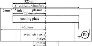
    Figure 1.  Schematic of 400mm RIE equipment chamber

  • 反应离子刻蚀变结构腔室采用升降机构实现承载台高度方向的连续变化, 调节极板间距离;进气口和出口的直径也可以调节,保证了承载台附近的气流均匀性;匀气腔、喷淋板、承载台和抽气口等如图 1所示,其中喷淋板上有7230个等效直径为1mm的通孔,承载台以15r/min的速率旋转。

  • 尺度较小、雷诺数小(层流)但流速慢是反应离子刻蚀腔室里的流动特点。流场模拟时,根据克努森数Kn的不同,可以采用连续假设或者分子假设。其中:

    式中,λ是气体分子的平均自由程;L是系统的特征长度尺度。描述流体时,如果Kn趋近于零,采用Euler方程来描述气体;Kn < 0.01时,可以用无滑移边界条件下的Navier-Stokes(N-S)方程;0.01 < Kn < 0.10时,可以用有滑移边界条件下的N-S方程;0.10 < Kn < 10时,属于过渡区;Kn>10时,采用分子假设,直接用波尔兹曼方程[19]

    对于低马赫数气体(小于0.3Ma),根据质量守恒定律[20-21],有方程:

    式中,ρ是控制体密度,V是控制体速度矢量。

    因为涉及热传递,根据能量守恒定律[20-21],有方程:

    式中,Pμ分别是作用在控制流体即气体上的压力和动力粘度,Sm是除压强源项以外的广义源项。

    Navier-Stokes方程[20-21]

    式中,T是温度场函数,uzur为气体的轴向流速和径向流速,keff为有效热传导系数,τ为粘性应力,Sh为体积力、辐射、化学反应等产生的内部热能。

    由雷诺数计算公式[20-21]

    式中,D为一特征长度,η表示黏性系数,v为气体的特征速率。可求得Re=0.5658,于是可以按层流模型计算。

    本文中Kn=0.032,介于0.01~0.10之间,属于滑移区流体,稀薄效应并不显著,此时气体分子的平均自由程比特征长度小很多,气体分子之间的碰撞仍起支配作用,符合连续假设的条件,但壁面附近克努森层变厚而使得物面无滑移边界条件失效,因此考虑建立滑移边界的N-S方程数值方法求解[19]。对于滑移流区的数值传热等问题,在满足工程计算精度的条件下,在主流区采用N-S方程方式求解[19],并对传统的N-S方程进行滑移边界条件修正,采用基于气体动力学的速度滑移加以修正[19]。假设vsTs分别为滑移速率与滑移温度,vwTw分别为壁面速率与壁面温度,则有如下关系式:

    式中,α为适应系数;[dv/dn]w为指向壁面速度的法向分量; T为温度, [dT/dn]w为指向壁面的温度梯度。在滑移壁面模式下,有效气体粘度μeff由努森数Kn给出,则:

    式中,ab为常数。

    喷淋板上均匀布置有7230个小孔,每个小孔直径为1mm,比腔室尺寸小大约3个数量级,精确构造真实结构比较困难,在建模时不宜直接计算,因此采用了多孔介质模型,由质量守恒定律和动量守恒定律[20-21]有:

    式中,F为外力等广义源项,Qb, εp, p2, βF为可选择的质量源项、孔隙率、渗透率、福希海默紊流定律系数,上标T表示转置。还需要考虑理想气体状态方程:

    式中,h0, p, T为总焓、压强、温度,E(Tρ)表示内能,R为理想气体常数。

    对于Ansys (Fluent)而言,流场和热传递模型是耦合计算的。本文中采用有限容积法(finite volume method,FVM)离散得到统一的控制方程,并利用插值的方法建立控制体及其边界物理量的关系,对离散的动量守恒方程组和连续性方程组采用SIMPLEC算法迭代求解速度场和修正压强场,反复多次循环计算直至收敛,最后用得到的速度场和相关系数求解温度场。

  • 实际的反应气体为O2和CHF3,其中O2的体积分数不小于0.8,是主要成分。忽略组分输运和化学反应的情况下,将气体流入口边界条件设置为单一的O2入口条件:O2入口流量为50cm3/min~250cm3/min,将出口处边界条件设为压强1.0Pa~2.5Pa,此外,冷却板为恒温285K,入口气体温度及腔室壁面温度均为298K。

2.   腔室流速、压强、温度分布分析
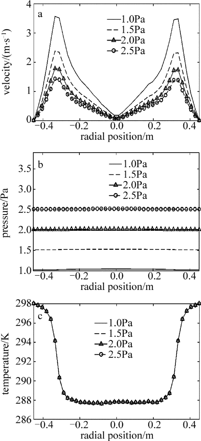
  • 基片晶圆厚度为8mm,图 2所示为腔室基片上方1mm处的截面流速、压强、温度分布云图。在工艺上,基片晶圆上方附近的流场与温度场分布特性是影响等离子体分布的重要因素,而影响流场(即压强和流速)与温度场分布的主要因素为工艺参量(如入口流量、出口压强等)与腔室结构几何参量(如极板间距离、进出口面积等)。

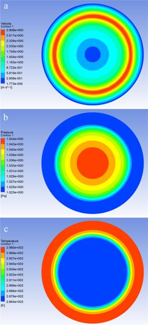
    Figure 2.  Contours of velocity, pressure and temperature at 1mm height cross-section above wafer

  • 根据前述所建立的仿真模型利用ANSYS(Fluent)软件进行仿真计算,取腔室轴对称面与基片晶圆上方1mm平面的交线上的流速、压强和温度数据。对于二氧化硅反应离子刻蚀工艺,气体流量相对较小且压强较低,为了保证刻蚀工艺有较高的均匀性,分别在50cm3/min, 100cm3/min, 150cm3/min, 200cm3/min, 250cm3/min的流量入口条件下和在1.0Pa, 1.5Pa, 2.0Pa, 2.5Pa出口压强条件下对腔室进行了仿真计算分析。

    当极板间距离d=60mm、出口压强1.0Pa时,仿真得到了入口流量50cm3/min~250cm3/min条件下的基片晶圆上方1mm处的速率、压强、温度分布,如图 3所示。结果表明, 在不同流量条件下压强与流速的分布特性相似,均保持着以腔室中心对称分布的特点,且基片上方附近流速和压强分布均随入口流量的增加而增大。反应腔室基片上方附近压强值由中心轴线处沿径向逐渐变小,在半径r=250mm处开始递减加快,直至冷却盘的边缘(r=325mm)。同时,当入口流量较小时,基片上方附近压强分布较均匀,并且基片附近压强分布随入口流量的增大而增大,中心轴线处的压强增加幅度更为突出。

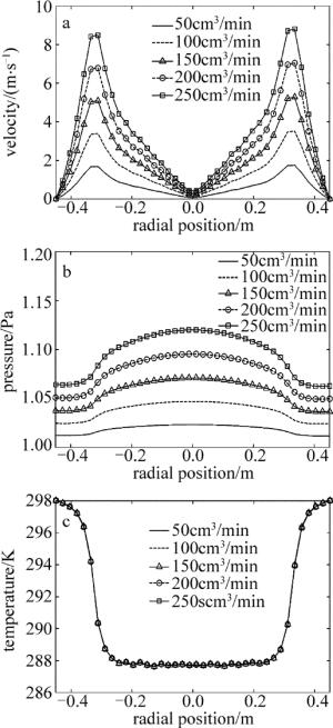
    Figure 3.  Gas flow velocity, pressure, temperature distribution at 1mm height cross-section above wafer under different inlet flow conditions

    在100cm3/min的流量且出口压强为1.0Pa~2.5Pa的条件下仿真得到极板间距离为60mm时的腔室内基片晶圆上方1mm处的速率、压强、温度分布如图 4所示。结果表明压强与流速在不同出口压强条件下的分布特性相似,保持着以腔室中心对称分布的特点,且基片上方附近流速分布随出口压强的增大而减小。而压强分布随出口压强的增大而增加,当出口压强较大时,基片上方附近压强分布比较均匀。

    Figure 4.  Gas flow velocity, pressure, temperature distribution at 1mm height cross-section above wafer under different outlet pressure conditions

    图 3c图 4c可以看出, 基片晶圆上方1mm处温度大面积均匀、稳定,且随入口流量和出口压强变化波动非常小。

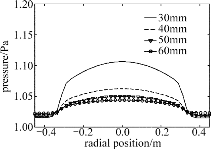
  • 反应腔室里的极板间距离、进口面积、出口面积也都会对压强均匀性进而对刻蚀均匀性产生重要影响,同时这些参量可以设计为用机械液压系统调节的。本文中针对不同极板间距离d(d=30mm,40mm,50mm,60mm)的腔室,以100cm3/min流量入口参量,分别仿真分析了各自基片晶圆上方1mm处的压强分布,分析结果如图 5所示。在下极板范围内,定义压强不均匀度[5]:

    Figure 5.  Pressure distribution at 1mm above wafer at different gap

    则当腔室极板间距离d=60mm时,K=2.02%;而当极板间距离d=30mm时,K=8.96%。显然,腔室极板间距离愈大,压强分布愈均匀。极板间距离d>60mm时腔室时对压强影响趋缓,这为极板间距离设定和优化提供了重要的依据。

    研究还发现,出口的面积和进气口面积也是影响压强分布的重要因素。当出口直径为50mm~250mm时,取流量100cm3/min,其压强分布如图 6所示。可以看出,直径在100mm以上时,压强变化较慢,而小于100mm,压强变化加快。当出口面积为0.0039m2、流量为50cm3/min~250cm3/min时,其压强分布如图 7所示。对比图 3b图 7可以看出,气体出口面积较小时,压强分布的均匀性有明显提高,压强不均匀度也由2.02%降低为0.81%。考虑到分子泵的安装,这为优化和设定抽气口的面积提供了一定的依据。当进气口直径为300mm~620mm时,取流量100cm3/min,其压强分布如图 8所示。可以看出, 直径在620mm时,压强变化幅度较小,而直径变小时,压强不均匀性变大,而进气口较大时,对喷淋板的布气均匀性提出了更高的要求。

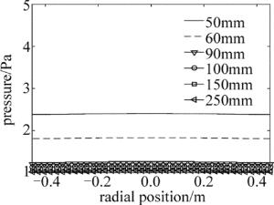
    Figure 6.  Pressure distribution at 1mm above wafer at different outlet diameters

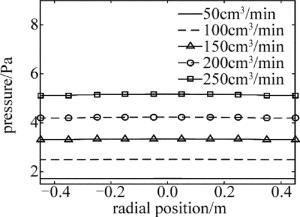
    Figure 7.  Pressure distribution at 1mm above wafer at the exit of 0.0039m2

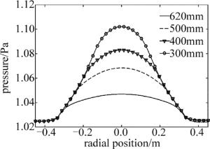
    Figure 8.  Pressure distribution at 1mm above wafer at different inlet diameters

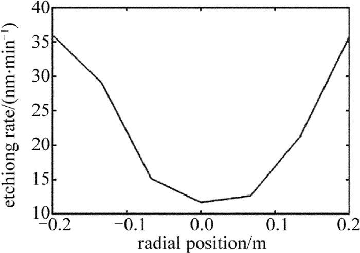
  • 为了验证仿真算法的准确性,在变结构腔室入口流量为100cm3/min、出口压强为1.0Pa时, 对二氧化硅进行了刻蚀实验,测得实验数据,并对比分析了腔室内气流压强和流速的径向分布。图 9为变结构腔室中内部测点的布置图, 其中腔室内测点在喷淋板下方。图 10为实验数据结果。

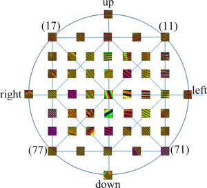
    Figure 9.  Sampling point distribution in pressure measurement in reactor chamber

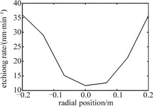
    Figure 10.  Result of the experiment

    影响刻蚀速率因素有气体成分和流量、射频功率、压强[22],而在其它条件固定不变时,压强或气体流速就是影响刻蚀速率的主要因素。计算仿真结果是气体速率随半径增大而增大,压强随半径增大而减小。而从实验结果来看,刻蚀速率随半径增大而增大,出口压强的测试结果和计算结果一致,都是1.0Pa。

3.   结论
  • 在对400mm反应离子刻蚀腔室气体流动建立连续流体和热传递模型的基础上,使用多物理场耦合分析计算软件对反应腔室中压强、流速和温度分布进行了仿真,研究了多种不同流量入口条件、不同出口压强条件、不同极板间距离以及不同进出口直径条件对气流分布与温度分布的影响。结果表明,对此上方喷淋进气、下方机械泵与涡轮分子泵抽气的高真空腔室,基片上方附近压强中心略高于边缘,且小流量时气流的均匀性较好。腔室极板间距离、出入口面积对压强分布也有较大影响,基片表面上方附近压强分布的均匀性随着腔室极板间距离的增加而提高,且随入口面积增加而提高、随出口面积减小也会有所提高。基片晶圆上方1mm处温度约为285K,且温度大面积均匀、稳定,不随入口流量、出口压强及腔室结构变化而变化,这表明此时反应腔室内基片晶圆附近的温度场均匀性以及稳定性都比较好。因此,选择合理的腔室极板间距离、进出气口面积是腔室结构设计和优化的重要一个环节。本文中的研究结果对大口径RIE腔室结构的优化设计及反应离子刻蚀工艺的控制具有重要的参考意义,反应离子刻蚀是一个包括诸多化学物理变化的复杂过程,还需要在考虑气体放电等的多物理场下进行进一步研究。

Reference (22)

Catalog

    /

    DownLoad:  Full-Size Img  PowerPoint
    Return
    Return