Advanced Search

ISSN1001-3806 CN51-1125/TN Map

Volume 44 Issue 1
Feb.  2020
Article Contents
Turn off MathJax

Citation:

Research of laser velocity measurement technology based on fast cross-correlation method with transfer function

  • Corresponding author: WANG Huilin, ckjs@sdut.edu.cn
  • Received Date: 2019-04-01
    Accepted Date: 2019-05-31
  • Laser measurement was the main method for velocity measurement of the moving objects such as conveyor belt and hot rolled steel plate. In order to improve measurement accuracy and response speed, system transfer correlation analysis velocity measurement technology was proposed. System transfer function of two signals between transmitter and receiver was calculated. Theoretical verification and experimental analysis were carried out by correlation analysis. The results show that, relative error is less than 0.1%. Laser velocity measurement system is constructed by correlation analysis of system transfer function instead of demodulation circuit to simplify signal conditioning circuit and reduce the uncertainty caused by circuit part. Fast correlation analysis is realized by cross-power spectral function method and transfer function of the system is obtained in frequency domain to improve the response speed of the system. By reasonably setting the distance between transmitters, sampling integration improves the measurement signal-to-noise ratio and reduces environmental uncertainty. The uncertainty of measurement is less than 0.2%. This research has certain guiding significance for the real-time measurement of conveyor belt speed.
  • 加载中
  • [1]

    HU G Sh. Digital signal processing: Theory, algorithms and implementation[M]. Beijing: Tsinghua University Press, 2003: 33-38(in Chinese).
    [2]

    PENG G. Speed measurement of automotive laser based on LabVIEW[J].Automation and Instrumentation, 2017, 32(10): 49-53(in Chin-ese).
    [3]

    GAO J. Research on laser velocity measurement system based on correlation measurement technology[D].Dalian: Dalian University of Technology, 2008: 2-4(in Chinese).
    [4]

    LIU X J, SONG Zh W, ZHANG W. Design and Implementation of the DSP-based real-time speeed measurement system by cross-correlation method[J].Information Technology and Network Security, 2011, 30(14): 90-92(in Chinese).
    [5]

    YANG X L. The system for laser cross-correlation velocity measurement based on DSP[J].Times Agricultural Machinery, 2016, 43(1): 40-42(in Chinese).
    [6]

    YANG M, CAI Ch G, LIU Zh H, et al. Research on the method of the triaxial primary vibration calibration using the heterodyne interfe-rometry[J]. Acta Metrologica Sinica, 2018, 39(2): 201-206(in Chinese).
    [7]

    SHARPE J P. A phase-stepped grating technique for frequency shifting in laser Doppler velocimetry[J].Optics and Lasers in Engineering, 2007, 45(11): 1067-1070. doi: 10.1016/j.optlaseng.2007.05.005
    [8]

    WANG K N, LIU Y L, CHEN H B, et al. Line-width measurement of DFB laser based on frequency shift delay self-heterodyning method[J]. Laser Technology, 2018, 42(5): 633-637 (in Chinese).
    [9]

    CASTELLINI P, MARTARELLI M, TOMASINI E P. Laser Doppler vibrometry: Development of advanced solutions answering to technology's needs[J]. Mechanical Systems & Signal Processing, 2006, 20(6): 1265-1285.
    [10]

    JIA F X, DING Zh L, YUAN F. Design on high frequency amplitude modulation of laser diode[J]. Infrared and Laser Engineering, 2007, 37(11): 1174-1177(in Chinese).
    [11]

    SHEN X. Laser Doppler velocimetry and application[M]. Beijing: Tsinghua University Press, 2004: 21-32(in Chinese).
    [12]

    DU Zh J, WANG H L. Study on measuring technology of vibration displacement based on optical-fiber acousto-optic modulation[J]. Laser Journal, 2015, 36(12): 85-87(in Chinese).
    [13]

    LIU L F, KONG F Q, YAN X L, et al. Feature analysis in correlation filtering tracker algorithm[J].Computer Engineering, 2018, 44(12): 264-270(in Chinese).
    [14]

    FU W, ZHU Y, ZHANG P, et al. Laser heterodyne interference micro-crack signal demodulation algorithm based on wavelet transform[J]. Journal of Test and Measurement Technology, 2018, 32(5): 369-373 (in Chinese).
    [15]

    CHEN L, LI X G, CHEN D R, et al. Research of laser velocimeter based on fractional fourier transform[J].Semiconductor Optoelectronics, 2016, 37(6): 886-889(in Chinese).
    [16]

    WANG Y D, YANG L Z, YANG Y Q. Temporal point spread functions measurement based on correlation of chaotic laser[J]. Laser & Optoelectronics Progress, 2018, 55(7): 71406(in Chinese).
    [17]

    ZHAO H B, ZHANG D, YANG J K, et al. Application of wavelet layered method for laser Doppler velocimetry signal[J]. Laser Technology, 2019, 43(1): 103-108 (in Chinese).
    [18]

    LI Y, YANG B J, TAN L, et al. The united detecting method of sampling integral and chaotic system for the weak periodic pulse signals[J]. Journal of Electronics & Information Technology, 2003, 25(12): 1653-1657(in Chinese).
    [19]

    ZHOU Sh D, MA Zh L. Influence of optical path collimation on measurement of long baseline transmittance meter[J]. Journal of Applied Optics, 2016, 37(1): 87-90 (in Chinese) doi: 10.5768/JAO201637.0103003
    [20]

    NI Y C. Practical measurement of uncertainty evaluation[M]. Beijing: China Metrology Press, 2008: 68-77(in Chinese).
  • 加载中
通讯作者: 陈斌, bchen63@163.com
  • 1. 

    沈阳化工大学材料科学与工程学院 沈阳 110142

  1. 本站搜索
  2. 百度学术搜索
  3. 万方数据库搜索
  4. CNKI搜索

Figures(5) / Tables(2)

Article views(6200) PDF downloads(1) Cited by()

Proportional views

Research of laser velocity measurement technology based on fast cross-correlation method with transfer function

    Corresponding author: WANG Huilin, ckjs@sdut.edu.cn
  • School of Mechanical Engineering, Shandong University of Technology, Zibo 255049, China

Abstract: Laser measurement was the main method for velocity measurement of the moving objects such as conveyor belt and hot rolled steel plate. In order to improve measurement accuracy and response speed, system transfer correlation analysis velocity measurement technology was proposed. System transfer function of two signals between transmitter and receiver was calculated. Theoretical verification and experimental analysis were carried out by correlation analysis. The results show that, relative error is less than 0.1%. Laser velocity measurement system is constructed by correlation analysis of system transfer function instead of demodulation circuit to simplify signal conditioning circuit and reduce the uncertainty caused by circuit part. Fast correlation analysis is realized by cross-power spectral function method and transfer function of the system is obtained in frequency domain to improve the response speed of the system. By reasonably setting the distance between transmitters, sampling integration improves the measurement signal-to-noise ratio and reduces environmental uncertainty. The uncertainty of measurement is less than 0.2%. This research has certain guiding significance for the real-time measurement of conveyor belt speed.

引言
  • 相关测量技术是非接触测量的方法之一,源于相关函数法,在不方便直接接触测量的场合中,非常适合恢复湮没在噪声中的微弱信号或者进行延时测量[1]。近年来,由于光电检测技术和数字信号处理技术的飞速发展,使得已经经历了50多年发展的相关测量技术更加完善[2]。1961年,英国人FIELD首次实现利用相关测量技术测量热轧带钢的速度。近年来,德国学者借助光学传感器和相关测量技术成功完成了传送带滑移率的在线测量[3]。由于国内对相关测量技术的研究较晚,因此其设计和制造水平相对落后,非接触测量设备大多需要进口,而且价格昂贵。相关测量技术研究能够满足国内工业需求,有助于提高我国高端产品的科技竞争力[4]。基于目前的相关测速技术理论,提出了基于高级精简指令集计算机(advanced RISC machines, ARM)内核的意法半导体(STMicroelectronics, STM)平台的相关测速系统,考虑相关测量技术处理微弱信号的优越性和激光的单色性、方向性,将相关测量和激光测速结合起来,对激光信号经过的系统的转递函数进行相关性分析,以传送带作为测速对象,验证方案的正确性和优越性。

1.   理论分析
  • 相关分析是信号处理中的重要方法,最基本的含义就是衡量两个信号的相似程度,也可以描述同一信号过去值与现在值之间的关系。如果利用相关来衡量两个信号的相似程度,即互相关,互相关函数式为:

    式中,rxy(τ)表示两个信号的互相关函数,x(t)和y(t)表示两个互相关分析的信号,T表示信号的时域长度,τ表示函数延时时间[5]。互相关函数rxy(τ)达到峰值时,两个信号的关联程度最大,所以相关最直接的物理意义是表征了信号的相似性。

    相关函数峰值对应延时τ0为渡越时间[5],若两束测量平行光之间的距离为D, 由下式可测得传送带速率:

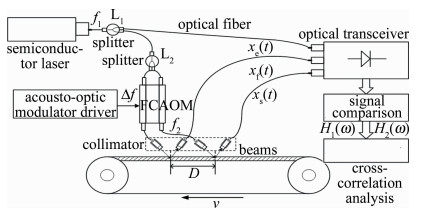
    为改善系统性能,参考信号与测量信号比较计算系统传递函数,取代接收端信号构建相关函数。激光器的发射频率f1激光经过光纤分光器L1,一路直接由光探测器接收[6],一路通过分光器L2,由多通道光纤耦合声光调制器频谱搬移后频率为f2,经光纤准直器以相距D准直光射出,传送带反射,再经过准直器耦合至光纤,与f1在光探测器混频。光探测器将光信号转换为差频电信号,调理电路实现电流-电压的转换,滤波和放大,使信号可以由处理器采样。

    光信号通过光探测器转换为余弦信号,相关法适用于处理余弦信号。f2的两路信号与f1比较,求得系统传递函数,进行相关函数分析,求得时延τ,由(2)式可得传送带速度,测速原理图如图 1所示。

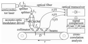
    Figure 1.  Principle diagram of velocity measurement

    光探测器输出信号为:

    式中, b0, b1b2为常数,表示光探测器接收不同谐波的增益,A1, A2表示光探测器对接收信号的增益,数值受探测器参量影响,f1为激光器发射的激光频率,f2为声光调制器频谱搬移的激光频率,电路响应频率低于f1f2,直流分量由电容滤除,则探测器输出差频[7]时,不变余弦信号为:

    式中,Δf为声光调制器调制频率[8],稳定在10.7MHz,Δφ为差频信号相位。对接收器接收的两路混频信号和中频信号进行傅里叶变换,得到:

    式中,$\mathscr{F}$表示对信号傅里叶变换,Xf(ω)和Xs(ω)为测量信号xf(t)和xs(t)的傅里叶变换,Xe(ω)为比较信号xe(t)的傅里叶变换,将参考信号和两路测量信号比较[9],在时域构建如下关系:

    由卷积定理,信号在频域的关系如下:

    式中,h1(t)和h2(t)为系统传递函数,通过傅里叶逆变换可以求得:

    根据(1)式,由传递函数h1(t)和h2(t)构建相关函数,得:

    找到相关函数的峰值,由(2)式求得速率。

2.   实验系统设计
  • 为实现稳定、便携的智能化测量,设计实验系统框图如图 2所示。

  • 激光具有单色性高、方向性和汇聚性好的特点,半导体激光器具有体积小、效率高和稳定性好的特点,稳定的信号源尤其是时不变信号有利于信号相关分析,因此选用半导体激光器作为光源,工作波长780nm,输出功率15mW。光电探测器选用硅光电二极管[10],响应波长600nm~1100nm。

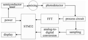
  • 光电探测器实现光信号-电信号的转换,输出光电流有信号调理电路处理[11]。电流-电压转换电路将输入电流信号转换为电压信号,电压信号通过跨阻型前置放大器放大,其具备噪声小、带宽大和稳定性高的优点,保证信号不会失真[12]。放大的电压信号通过带通滤波器,将无用信号滤除。后置放大器比前置放大器具有更高的增益,保证处理器能够采样信号,信号调理电路框图如图 3所示。

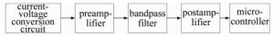
    Figure 3.  Block diagram of signal conditioning circuit

    信号的调理电路应完全相同,保证传递函数只与传送带位置有关,防止信号调理电路引起传递函数的改变,影响测速系统的测量准确性。

  • 根据测速系统硬件设计,进行微处理器的程序编写,软件部分采用模块化设计,有利于程序在不同平台的移植和稳定运行[13]。系统的软件部分划分为3个模块:初始化模块、数据处理模块和显示模块。系统软件设计的流程图如图 4所示。

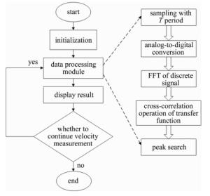
    Figure 4.  Flow chart of system software

    数据处理模块实现信号传递函数的相关分析,搜索使相关函数达到峰值的延时[14],即渡越时间,根据渡越时间测量传送带的速度。考虑本系统计算传递函数在频域进行,采用互功率谱密度函数法计算渡越时间,互功率谱密度函数与互相关函数是傅里叶变换的关系[15],以此实现快速相关计算。

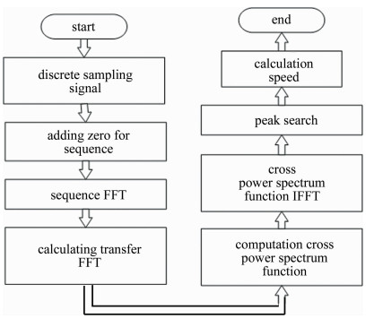
    (1) 模数转换器(analog-to-digital converter, ADC)按时间间隔T对光电探测器接收的信号xf(t), xs(t)和xe(t)采样,离散为长度不同的序列xf(n), xs(n)和xe(n)。

    (2) 对3个序列补零使序列长度相同[16],序列长度应为2m,得到新的序列xf′(n), xs′(n)和xe′(n)。

    (3) 对补零后的序列快速傅里叶变换(fast Fourier transformation, FFT),得Xf(k), Xs(k)和Xe(k)。由卷积定理可计算出系统传递函数的傅里叶变换H1(k), H2(k)。

    (4) 求H1(k)的共轭H1*(k),并和H2(k)相乘得Rxy(k):

    式中,Rxy(k)为互功率谱密度函数[17]

    (5) 由维纳-辛钦定理, 得:

    Rxy(k)进行逆快速傅里叶变换(inverse fast Fourier transformation, IFFT),得到互相关函数rxy(τ)。

    (6) 峰值搜索最大值rxy(τ0),τ0表示函数最大值时的延时。由(2)式计算传送带的速率, 数据处理模块流程图 5所示。

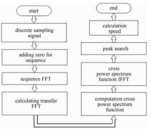
    Figure 5.  Flow chart of data processing module

3.   实验结果
  • 对系统实验,将驱动传送带的电机转速转换为线速度作为标准,设定两束测量平行光距离D=15mm,选用50kHz的采样频率和4096点的采样点数测量传送带速度,对比测量结果和标准速度值,测试实验结果如表 1所示。

    number standard velocity/(m·s-1) measure velocity/(m·s-1) deviation/
    (m·s-1)
    1 1.029 1.021 -0.008
    2 2.015 1.999 -0.016
    3 3.026 3.046 0.020
    4 4.022 3.996 -0.026
    5 4.986 5.010 0.024

    Table 1.  Conveyor belt velocity data (before the enhancements)

    传送带速率平均值为S1=3.0156m/s, 系统测得速率平均值为S2=3.0138m/s, 系统的相对误差为:

  • 实验表明:D>20mm时,系统响应时间大于0.01s;D < 4mm时,测量误差高于1%。为优化响应速率和提高精度,设定D=7mm。在此基础上采用取样积分技术滤除干扰噪声,对连续N个周期的同一部分信号累加平均,由于噪声大多是非周期信号,因此会得到抑制[18],抑制程度取决于积累次数。

    采用模拟多点信号平均器,具有稳定性高、复现波形频率高的优点。参量选择每个周期取样512个点,有效积分时间1ms,取样脉宽0.2ns,则取样积分积累次数为5×10⁶,信噪比有所改善,并且控制系统测量时间小于0.01s,改进后的系统实验数据如表 2所示。

    number standard velocity/(m·s-1) measure velocity/(m·s-1) deviation/
    (m·s-1)
    1 0.986 0.985 -0.001
    2 2.073 2.069 -0.004
    3 3.043 3.038 -0.005
    4 3.999 4.006 0.007
    5 4.995 4.006 0.011

    Table 2.  Conveyor belt velocity data (after the enhancements)

    由(17)式计算,改进后的系统相对误差为0.0529%,系统得到优化。

4.   不确定度评定
  • (1) 激光光源引起的不确定度u(s)。系统选择波长780nm的半导体激光器,光源稳定性小于0.06%,用矩形分布估计其不确定度为3.45×10⁻⁴

    (2) 光电探测器引起的不确定度u(r)。选择响应波长为600nm~1100nm的硅光电探测器,扩展不确定度为0.08%,置信概率p=99%,包含因子k=2576, 可得由光电探测器导致的不确定度为3.64×10⁻⁴

    (3) 信号调理电路引起的不确定度u(p)。经过误差实验,测量得电路部分的误差不高于0.05%,由正态分布估计不确定度为2.39×10⁻⁴

    (4) 外界杂散光引起的不确定度u(l)。两束测量平行光距离D设置存在误差,引起测量不确定度[19],误差小于0.04%,反正弦分布评定不确定度为2.81×10⁻⁴

    (5) 环境因素引起的不确定度u(c)。系统测量结果受外界温度、气压、湿度的影响,实验表明, 这部分误差占总体的0.08%, 矩阵分布估计不确定度为4.66×10⁻⁴

    则合成不确定度为[20]:

    由(18)式计算可知不确定度小于0.2%,到达高精度的要求。

5.   结论
  • 提出对系统传递函数相关分析测量速度,并给出硬件设计和互功率谱密度函数法的软件设计。相关法处理余弦信号效率较高,系统传递函数的相关分析简化了信号处理电路的设计,降低了成本,互功率谱密度函数法求渡越时间有利于在频域的信号处理,减少了系统响应时间,取样积分的应用提高了系统的精度。通过实验证明了方法的高分辨度和稳定性,具备可行性。为工业应用中非接触测速提供了有效方法,具有巨大的研究空间和应用价值。

Reference (20)

Catalog

    /

    DownLoad:  Full-Size Img  PowerPoint
    Return
    Return