Advanced Search

ISSN1001-3806 CN51-1125/TN Map

Volume 43 Issue 6
Nov.  2019
Article Contents
Turn off MathJax

Citation:

Numerical simulation of laser cutting composite anodes for lithium-ion batteries

  • Corresponding author: ZHANG Yi, zy@hnu.edu.cn
  • Received Date: 2018-12-11
    Accepted Date: 2019-01-03
  • In order to investigate cutting characteristics of negative plate composites, the temperature field of negative plate composite material of the lithium ion battery by laser cutting was numerically simulated based on finite element model. The size of the width and depth of the negative electrode slit was obtained from the temperature field distribution. The effect of laser power, cutting speed and spot radius on the slit width and depth of negative surface material was studied. The results show that, the width of the slit on the surface of the negative electrode increases with the increase of laser power and the radius of the spot. It decreases with the increase of cutting speed. The slit depth increases with the increase of laser power. It decreases with the increase of cutting speed and spot radius. After cutting to the middle copper foil, the change rate of the slit depth is slowing down. The composite structure of the negative electrode material has a significant effect on the depth of the slit. When the power is 170W, the radius of the spot is 47μm, and the cutting speed varies to about 600mm/s, the effect is most obvious. The cutting depth reaches 60μm under this parameter. After breaking through this threshold, the growth rate is increased significantly until the polar plate is completely cut off. The results can provide a reference for laser cutting of lithium ion battery plate composite material.
  • 加载中
  • [1]

    PETERSON S B, WHITACRE J F, APT J. Net air emissions from electric vehicles: the effect of carbon price and charging strategies[J]. Environmental Science & Technology, 2011, 45(5):1792-1797.
    [2]

    LIAO X, YU J, GAO L.Electrochemical study on lithium iron phosphate/hard carbon lithium-ion batteries[J]. Journal of Solid State Electrochemistry, 2012, 16(2):423-428. doi: 10.1007/s10008-011-1387-7
    [3]

    KOJIMA T, ISHIZU T, HORIBA T, et al. Development of lithium-ion battery for fuel cell hybrid electric vehicle application[J]. Journal of Power Sources, 2009, 189(1):859-863. doi: 10.1016/j.jpowsour.2008.10.082
    [4]

    SCROSATI B, JVRGEN G. Lithium batteries: Status, prospects and future[J]. Journal of Power Sources, 2010, 195(9):2419-2430. doi: 10.1016/j.jpowsour.2009.11.048
    [5]

    YANG L X, PENG X F, WANG B X. Numerical modeling and experimental investigation on the characteristics of molten pool during laser processing[J]. International Journal of Heat and Mass Transfer, 2001, 44(23):4465-4473. doi: 10.1016/S0017-9310(01)00086-2
    [6]

    CENG W M S M. Laser material processing[M]. London, UK:Springer, 2010:21-27.
    [7]

    LEE D, PATWA R, HERFURTH H, et al.High speed remote laser cutting of electrodes for lithium-ion batteries: Anode [J].Journal of Power Sources, 2013, 240:368-380. doi: 10.1016/j.jpowsour.2012.10.096
    [8]

    PFLEGING W. A review of laser electrode processing for development and manufacturing of lithium-ion batteries[J]. Nanophotonics, 2017, 7(3):549-573.
    [9]

    SCHMIEDER B. Laser cutting of graphite anodes for automotive lithium-ion secondary batteries: Investigations in the edge geometry and heat-affected zone[C]// Laser-based Micro- & Nanopackaging & A-ssembly Ⅵ. New York, USA: International Society for Optics and Photonics, 2012: 31-56.
    [10]

    KRONTHALER M R, SCHLOEGL F, KURFER J, et al. Laser cutting in the production of lithium ion cells[J]. Physics Procedia, 2012, 39:213-224. doi: 10.1016/j.phpro.2012.10.032
    [11]

    DEMIR A G, PREVITALI B. Remote cutting of Li-ion battery electrodes with infrared and green ns-pulsed fibre lasers[J]. The International Journal of Advanced Manufacturing Technology, 2014, 75(9/12):1557-1568.
    [12]

    PFLEGING W. Laser cutting of graphite anodes for automotive lithium-ion secondary batteries: Investigations in the edge geometry and heat-affected zone[J]. Proceedings of the SPIE, 2012, 8244:23-27.
    [13]

    LEE D, PATWA R, HERFURTH H, et al. Parameter optimization for high speed remote laser cutting of electrodes for lithium-ion batte-ries[J]. Journal of Laser Applications, 2016, 28(2):022006. doi: 10.2351/1.4942044
    [14]

    KURFER J, WESTERMEIER M, TAMMER C, et al. Production of large-area lithium-ion cells—Preconditioning, cell stacking and quality assurance[J]. CIRP Annals-manufacturing Technology, 2012, 61(1):21-32. doi: 10.1016/j.cirp.2012.03.121
    [15]

    WANG Y Sh, YANG X Ch, LIU Y J. Temperature field of laser scanning line facula[J]. Chinese Journal of Lasers, 2006, 33(7):981- 986(in Chinese).
    [16]

    LIU X X, HUANG R, YAO G, et al. Numerical simulation of the temperature field of laser butt welding of titanium alloy sheet[J]. Laser Technology, 2013, 37(5): 700-704(in Chinese).
    [17]

    MA J, ZHAO Y, ZHOU F Y, et al. Study on temperature field of materials irradiated by pulse laser based on FEM [J]. Laser & Infrared, 2015, 45 (1): 27-31(in Chinese).
    [18]

    YILBAS B S, ARIF A F M, ALEEM B J A. Laser cutting of sharp edge: Thermal stress analysis[J]. Optics & Lasers in Engineering, 2010, 48(1):10-19.
    [19]

    DENG D Sh, LIU J H, HU X Y, et al. Steady-state conditions for oxygen assisted lasox laser cutting of thick plates[J]. Laser Technology, 2003, 27(3):178-181(in Chinese).
    [20]

    NYON K Y, MOKHTAR M, ABDUL-RAHMAN R. Finite element analysis of laser inert gas cutting on Inconel 718[J]. International Journal of Advanced Manufacturing Technology, 2012, 60(9/12):995-1007.
    [21]

    YANG H L, JIN X Zh, XIU T F, et al. Numerical simulation of fiber laser welding of steel /aluminum dissimilar metals[J]. Laser Technology, 2016, 40(4):606-609(in Chinese).
  • 加载中
通讯作者: 陈斌, bchen63@163.com
  • 1. 

    沈阳化工大学材料科学与工程学院 沈阳 110142

  1. 本站搜索
  2. 百度学术搜索
  3. 万方数据库搜索
  4. CNKI搜索

Figures(10) / Tables(1)

Article views(7413) PDF downloads(37) Cited by()

Proportional views

Numerical simulation of laser cutting composite anodes for lithium-ion batteries

    Corresponding author: ZHANG Yi, zy@hnu.edu.cn
  • 1. Shenzhen Research Institute, Hunan University, Shenzhen 518057, China
  • 2. Key Laboratory of Intelligent Laser Manufacturing in Hunan Province, Hunan University, Changsha 410082, China
  • 3. Shenzhen Geesun Intelligent Technology Co. Ltd., Shenzhen 518101, China

Abstract: In order to investigate cutting characteristics of negative plate composites, the temperature field of negative plate composite material of the lithium ion battery by laser cutting was numerically simulated based on finite element model. The size of the width and depth of the negative electrode slit was obtained from the temperature field distribution. The effect of laser power, cutting speed and spot radius on the slit width and depth of negative surface material was studied. The results show that, the width of the slit on the surface of the negative electrode increases with the increase of laser power and the radius of the spot. It decreases with the increase of cutting speed. The slit depth increases with the increase of laser power. It decreases with the increase of cutting speed and spot radius. After cutting to the middle copper foil, the change rate of the slit depth is slowing down. The composite structure of the negative electrode material has a significant effect on the depth of the slit. When the power is 170W, the radius of the spot is 47μm, and the cutting speed varies to about 600mm/s, the effect is most obvious. The cutting depth reaches 60μm under this parameter. After breaking through this threshold, the growth rate is increased significantly until the polar plate is completely cut off. The results can provide a reference for laser cutting of lithium ion battery plate composite material.

引言
  • 近年来,混合动力汽车、电动汽车、手机等移动设备对电池性能的需求日益趋增[1],锂离子电池因其具有可重复充电的特性和高能量密度、低成本、使用周期长[2]等优点,广泛应用于电动汽车、移动设备和能源存储等领域[3]。然而,锂离子电池性能也受到制造工艺的影响,对内部卷绕极片的制造工艺具有较高的要求。锂离子电池的主要组成部分中包括薄片状的极片材料,其典型结构为石墨涂覆的铜正极极片和锂金属氧化物涂覆的铝负极极片[4]。激光切割电池极片在其加工行业中占主导地位,具有无接触加工、切割路径灵活和切割效率高等特点[5],能克服机械切割方法的缺陷[6]。LEE等人对激光切割锂离子电池集流体进行了模拟和实验研究,通过单模光纤激光切割集流体和单面涂覆极片的实验验证了模型的合理性,表明铜集流体切割是一个依赖激光强度和作用时间的过程,而铝集流体切割更依赖于激光强度。PFLEGING还建立了激光远程高速切割负极极片的3维数学模型,分析了切割过程中的热传递、成分变化、熔池流动、反冲压力、多重反射等物理现象[8]。SCHMIEDER[9]使用了高速摄影技术来研究激光切割电极,提出了一个理论模型以理解电极表面涂层的烧蚀机理。KRONTHALER等人[10]通过对横截面几何参量的测量评估了激光切割电极极片的切割边缘质量。DEMIR等人[11]研究了红外激光和绿激光切割电极的质量,分析了加工条件,指出应按照不同需求选择切割所用的激光光源。PFLEGING[12]建立了切割边缘几何结构的分析模型,研究了脉冲宽度对热影响区(heat affect zone, HAZ)成分的影响。LEE等人[13]从实验上对激光高速远程切割极片的参量进行了优化,获得了可接受的切割质量。

    本文中采用有限元方法对激光切割锂离子电池负极极片过程展开温度场模拟分析,通过温度场分布获得切缝特征数值,探究激光工艺参量对切缝宽度及切缝深度的影响规律,并分析了极片复合结构对传热规律的影响。本研究可为研究激光切割锂离子电池极片切缝特征提供参考,对提高激光电池极片切割质量具有重要意义。

1.   有限元模型的建立
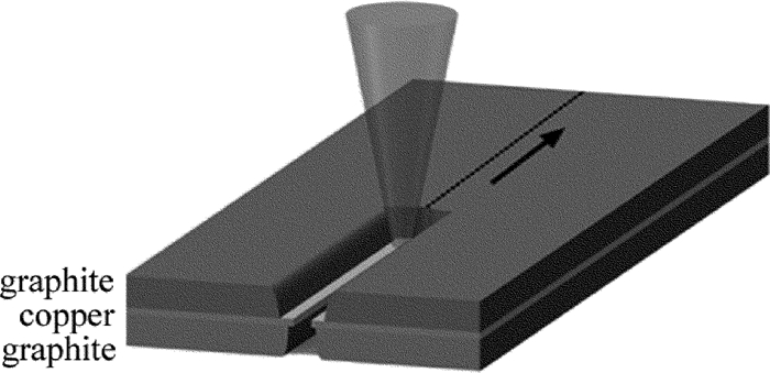
  • 研究对象为锂离子电池负极极片材料,该材料为“三明治”结构,由铜箔及其上下表面涂覆的等厚度石墨层组成,材料总厚度为100μm,其中铜箔厚度为10μm,材料结构如图 1所示。切割过程中,激光束辐照至负极材料上表面,上层石墨材料吸收能量后温度迅速上升至气化点,同时热量传导至中间金属层与下层石墨,产生材料的去除[14]。通过扫描振镜控制激光光斑位置,调整其沿切割路径连续移动,由此完成切割过程[15]

    Figure 1.  Schematic diagram of anode structure

    激光切割过程中,光斑所在区域的温度随时间急剧变化,激光切割温度场求解属于非线性的瞬态导热问题。温度场分析基于能量控制方程,利用傅里叶定律和能量守恒定律建立导热微分方程求解,求得内部各点的热流密度矢量,获得材料体内的温度场。为简化计算条件,提出3点假设[16]:(1)材料是各向同性的连续介质;(2)考虑材料物性参量(导热率、比热以及密度大小)的温度依赖性;(3)忽略石墨层与铜箔间的热损耗以及热阻的影响。

  • 在激光与材料的作用过程中,温度t随时间τ变化,属于非稳态导热,直角坐标系中3维非稳态导热微分方程的一般形式为[17]

    式中,ρ(kg/m3)为材料的密度,c为材料的比热容,λ[W/(m·K)]为材料的热导率,q′为内热源。根据本节中对模型材料常物性的假设,对应该模型的导热过程,可将导热微分方程简化为物性参量为常数、无内热源的傅里叶方程,即:

    式中,a=λ/(ρc), x, y, z为空间坐标。

  • 初始条件下,设置初始温度t0=283.97K。由于材料在激光烧蚀过程中温度急剧升高,其温度变化还需考虑光斑辐照区域与周围介质间的对流换热与辐射换热。因此,在激光热源辐照区域内,激光热源以热流密度形式加载在材料上表面,除此之外,所有表面均设置为对流换热边界与辐射换热边界,热传递量q的对流边界条件[18]可表示为:

    式中,Δt指极片材料表面与空气流体间的温度差,h表示表面换热系数。

    材料的辐射边界条件,即极片与周围空气间的热传递量q可以表示为:

    式中,ε为辐射系数,取ε=0.7,S表示极片材料的面积,tm为材料温度,ta为周围空气的温度,初始条件下,tm=ta=283.97K, 斯忒藩-玻尔兹曼常数σ=5.67×10⁻⁸W(m2·K4)。

    激光切割过程中,温度的高低、温度梯度的大小取决于板材的受热面积、板材吸收的热流密度和加热时间[19-20],除(3)式、(4)式所表达的对流边界条件和辐射边界条件外,将激光热源视为施加于材料表面的一类边界条件。本文中的研究对象为厚度约100μm的负极极片材料,高斯热源模型可描述其切割温度场的分布。高斯热源模型是一种面热源,切割过程中通过激光热源的加载为材料去除提供热能,其中表面有效加载区域为光斑。加热区域内热流密度近似为高斯函数分布,热源S0的数学表达式[20]如下:

    式中,γs为材料表面的反射系数,δ为材料沿厚度方向的吸收率,(x0, y0)为光斑中心坐标,r0为光斑半径,I0为光斑中心强度, P为激光功率。根据高斯分布理论,光斑中心强度可表示为:

    入射激光波长为1065nm,该条件下石墨和铜的材料特性参量如表 1所示。为准确地模拟复合材料的特性,表面吸收性质与水平面传播方向上的热传导表现为石墨材料的性质。

    properties copper graphite
    density/(kg·m-3) 8.96×10³ 1.73×10³
    thermal conductivity/(W·m-1·K-1) 317 18.1
    specific heat/(J·kg-1·K-1) 385 2092.48
    surface reflectance 0.97267 0.16815
    melting temperature/K 1358 3652
    boiling temperature/K 2835 4800

    Table 1.  Material properties of copper and graphite

  • 仿真过程为3-D瞬态热分析,采用ANSYS solid 90单元,适用于3-D的稳态或瞬态热分析问题。如图 2所示,该单元为3-D 20个节点的热实体,每节点具有一个温度自由度。采用扫掠方式划分六面体网格,按照载荷特征,根据网格与切缝的距离决定划分精度,由外向内逐渐提高,对切缝部分的网格进一步细化,该模型一共具有5252个节点,3600个单元[21]。考虑到切缝两侧的对称性,故只取切缝一侧进行求解。由此建立材料3-D模型,其尺寸为1mm×0.5mm×0.1mm。
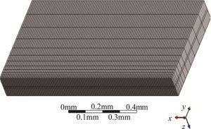
    Figure 2.  Meshing

2.   切割模型的数值模拟
  • 采用波长为1065nm激光切割负极极片材料,扫描电子显微镜下, 切缝一侧如图 3所示。可观察到切缝边缘存在分层现象,即表层石墨切缝宽度大于中间铜箔的切缝宽度。同时,铜箔边缘存在熔化现象而表层石墨边缘未发现此现象。由此可推测激光极片切割过程中,金属铜箔发生了熔化切割,同时伴随部分气化切割,而表层石墨被气化去除。

    Figure 3.  Melting of copper foil on anode kerf edge (500×, part 1000×)

    在此基础上,为直观表达模拟结果的规律,建立求解结果中温度分布与实际切割后的切缝特征的联系,对应切割过程中材料去除区域,采用特定方法量取切缝深度ha、切缝宽度wa的值。

    表 1的材料热特性参量可知,铜的熔点为1358K,石墨的气化点为4800K,切割过程中金属铜箔发生了熔化切割,而表层石墨被气化去除,则可认为铜与石墨材料分别达到熔点与化点时受热,形成相变区域。由此于温度场云图中以4800K的等温线为边界,定义温度高于4800K部分为该模型的材料去除区域,即量取温度云图在石墨气化温度分界点与光斑中心之间的距离,作为切缝特征的表征。图 4为在激光切割负极极片的温度场云图求解结果中切缝深度ha、切缝宽度wa的测量方法。当极片材料底面的温度达到气化点时,则认为该极片已被完全切断。

    Figure 4.  Schematic diagram of kerf feature

  • 为探究各参量对切缝特征的影响,使用不同参量对温度场分布进行求解,获得工艺参量对切缝宽度wa的影响规律。

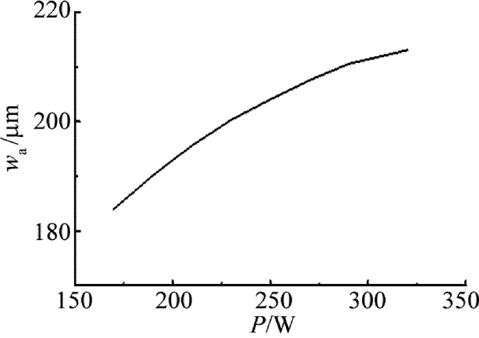
    切割速率v=600mm/s、光斑半径Ra=47μm时, 激光功率对表层石墨的切缝宽度wa的影响规律如图 5所示,切缝宽度wa随激光功率上升逐渐增大。随着激光功率上升,光斑辐照区域内表层石墨吸收的能量增加,导致传导至辐照区域附近的能量上升,使其受热气化形成更宽的切缝。

    Figure 5.  Relationship between kerf width and laser power under v=600mm/s, Ra=47μm

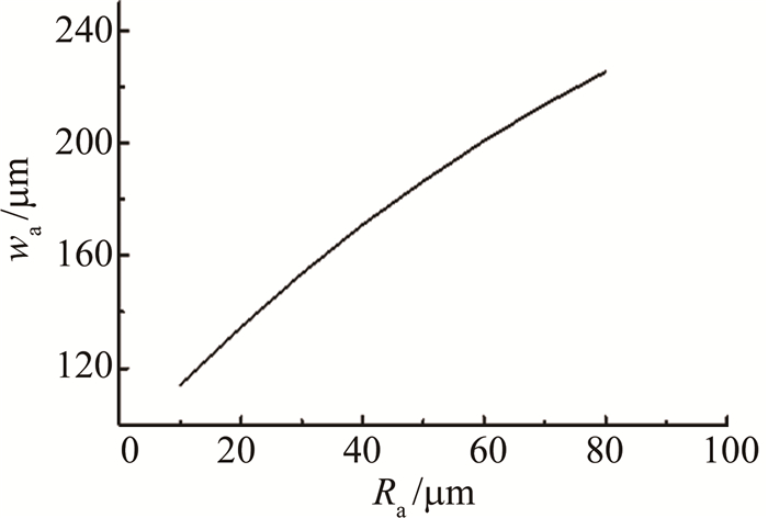
    图 6为切割速率v=600mm/s、功率P=170W时,表层石墨切缝宽度wa随光斑半径Ra的变化规律。随光斑半径Ra逐渐增大,切缝宽度值随之增加。光斑半径增大,光斑辐照区域范围增大,在光斑能量密度减小至无法去除材料之前,切缝宽度亦随之增加。

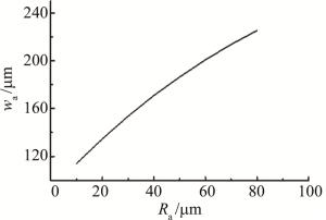
    Figure 6.  Relationship between kerf width and laser spot radius under P=170W, v=600mm/s

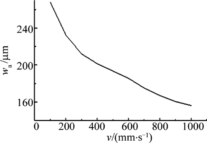
    激光功率P=170W、光斑半径Ra=47μm时,切割速率对切缝宽度wa的影响规律如图 7所示。在其余参量保持不变的情况下,随着切割速率逐渐增大,激光与表层石墨材料的作用时间相对减少,材料内部不能及时传热,导致切缝宽度wa减小。

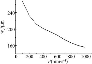
    Figure 7.  Relationship between kerf width and cutting speed under P=170W, Ra=47μm
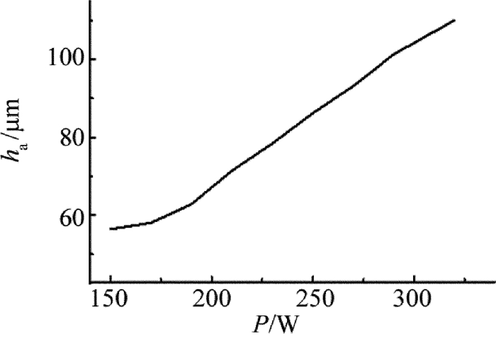
  • 不同激光功率下的切缝深度ha图 8所示。功率为150W~170W时,激光烧蚀金属铜箔,切缝深度增长趋势缓慢。功率大于170W时,烧蚀区域突破了中间铜箔,高于这一阈值点后,切缝深度增长速率明显增大。

    Figure 8.  Relationship between kerf depth and laser power under v=600mm/s, Ra=47μm

    图 9表示激光功率P=170W、切割速率v=600mm/s条件下,激光光斑半径对切缝深度的影响规律。由图 9可知,切缝深度随光斑半径增加而减小。激光能量密度随着光斑半径增大而减小,导致激光的材料去除率下降,切缝深度减小。

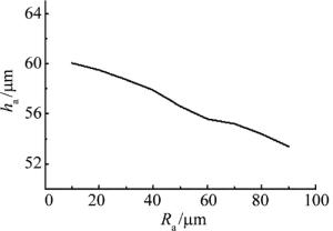
    Figure 9.  Relationship between kerf depth and laser spot radius under P=170W, v=600mm/s

    激光功率P=170W、光斑半径Ra=47μm时,切割速率变化对切缝深度的影响规律如图 10所示。显然,切缝深度随着切割速率的增大逐渐减小。切割速率大于600mm/s时,切缝深度均低于60μm,换言之,在此范围内切缝深度始终无法穿透铜箔,其变化速率缓慢。当速率小于600mm/s、切缝深度大于60μm后,切缝深度变化速率发生明显变化。随切割速率进一步减小,切缝深度上升速率增快,切割速率降至300mm/s时负极极片完全切断。由于铜箔的热导率远大于石墨而激光吸收率远小于石墨,铜箔的材料去除率低,烧蚀阈值高于石墨,因此,激光熔透中层铜箔需要更长的作用时间,当切割速率减小至可穿透铜箔阈值,随着切割速率的进一步降低,切缝深度陡增,直至切断。

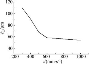
    Figure 10.  Relationship between kerf depth and cutting speed under P=170W, Ra=47μm

3.   结论
  • 采用有限元数值方法对锂离子电池电极复合材料进行了数值模拟研究,通过建立极片复合材料的有限元模型,由温度场分布输出负极切缝宽度与切缝深度的尺寸大小。探究了激光功率、光斑半径、切割速率对切缝宽度及切缝深度的影响,并通过切缝深度的变化规律分析了负极极片材料的复合结构对传热的影响。

    (1) 切缝宽度随激光功率的增大、切割速率的减小和激光光斑半径的增大而增大。

    (2) 增大激光功率、减小切割速率和减小激光光斑半径能获得更深的切缝。

    (3) 材料的复合结构对热传导产生一定影响,表现为切缝深度变化速率在表层石墨与中间铜箔分界面处出现明显变化。由于铜箔层激光吸收率小、热导率大,激光烧蚀中间铜箔层时热量被迅速传导至周围区域,导致铜箔去除缓慢,而烧蚀石墨层时热量更多的用于材料去除,因此切缝深度变化速率发生变化。

Reference (21)

Catalog

    /

    DownLoad:  Full-Size Img  PowerPoint
    Return
    Return