Advanced Search

ISSN1001-3806 CN51-1125/TN Map

Volume 43 Issue 4
Jul.  2019
Article Contents
Turn off MathJax

Citation:

Crack detection based on laser ultrasound diffraction transverse wave

  • Received Date: 2018-09-10
    Accepted Date: 2018-12-21
  • In order to evaluate surface breaking cracks, laser ultrasonic diffraction shear wave method was used to measure its parameters. Laser-induced shear wave propagating to the crack tip produced a diffraction signal and then the signal was received by the sensors on the other side of the crack. According to the transit time of diffracted shear waves at different receiving points, the formulas for calculating crack parameters were derived. The propagation process of the shear wave in the workpiece was simulated and analyzed. The experimental system of laser-ultrasonic crack measurement was established. The diffraction shear wave data were also collected. The experimental results show that, within the effective detection range, the error between the measured value and the actual value is within 5%. The results can promote the application of laser ultrasound in surface crack detection.
  • 加载中
  • [1]

    GÓMEZ M J, CORRAL E, CASTEJÓN C, et al. Effective crack detection in railway axles using vibration signals and WPT energy[J]. Sensors, 2018, 18(5):1603. doi: 10.3390/s18051603
    [2]

    HE B Y, SOADY K A, MELLOR B G, et al. Fatigue crack growth behavior in the LCF regime in a shot peened steam turbine blade material [J]. International Journal of Fatigue, 2016, 82(2):280-291.
    [3]

    ZHU H L, LIU Ch, ZHANG B, et al. Research on laser ultrasonic visual image processing [J]. Chinese Journal of Lasers, 2018, 45(1): 01040004(in Chinese).
    [4]

    MI B, UME I C. Parametric studies of laser generated ultrasonic signals in ablative regime: Time and frequency domains [J]. Journal of Nondestructive Evaluation, 2002, 21(1): 23-33. doi: 10.1023/A:1019980725994
    [5]

    MA J, ZHAO Y, ZHOU F Y, et al. Effect of defocusing amount on thickness measurement based on laser ultrasound[J]. Laser Technology, 2015, 39(3): 349-352(in Chinese).
    [6]

    LEE S E, LIU P P, KO Y W, et al. Study on effect of laser-induced ablation for Lamb waves in a thin plate [J]. Ultrasonics, 2019, 91:121-128. doi: 10.1016/j.ultras.2018.07.019
    [7]

    XU Zh X, HUANG J H, WANG Zh G, et al. Numerical study on coated metal surface crack by laser ultrasonic detection[J]. Laser Technology, 2018, 42(6): 801-805(in Chinese).
    [8]

    CAO J Sh, CAO Zh, ZHAO L F, et al. Detecting techniques of surface crack of pipeline based on laser ultrasonic[J]. Opto-Electronic Engineering, 2016, 43(3):1-6(in Chinese).
    [9]

    CHOI Y S, JEONG H, LEE J R. Laser ultrasonic system for surface crack visualization in dissimilar welds of control rod drive mechanism assembly of nuclear power plant [J]. Shock and Vibration, 2014, 10(1):1-10.
    [10]

    LIU Z H, FENG X J, CHEN H L, et al. Experimental research on defect detection of laser-induced Lamb waves based on wavenumber analysis[J]. Journal of Mechanical Engineering, 2018, 54(18):23-32(in Chinese). doi: 10.3901/JME.2018.18.023
    [11]

    LI K S, MA Zh Y, FU P, et al. Quantitative evaluation of surface crack depth with a scanning laser source based on particle swarm optimization-neural network [J]. NDT & E International, 2018, 98: 208-214.
    [12]

    WANG M Y, ZHOU Y J, GUO Ch. Numerical simulation of laser ultrasonic detection of surface micro-crack depth[J]. Laser Technology, 2017, 41(2):178-181(in Chinese).
    [13]

    SHEN Zh H, LI J, NI Ch Y, et al. Numerical simulation and experimental study on surface acoustic waves interacting with cracks heated by scanning heating laser source[J]. Journal of the Acoustical Society of America, 2012, 131(4):3477.
    [14]

    MA J, ZHAO Y, SUN J H, et al. Experimental study on ultrasonic bulk field induced by oblique laser[J]. High Power Laser & Particle Beams, 2015, 27(9):301-306(in Chinese).
    [15]

    FENG W W, JIN L, ZHAO J F, et al. Mode conversion of laser-excited shear waves interaction with the side of vertical cracks[J]. Laser Technology, 2018, 42(4): 487-493(in Chinese).
    [16]

    NDT BRANCH OF THE CHINESE ACADEMY OF MECHANICAL ENGINEERING. Ultrasonic testing [M].Beijing: Machinery Industry Press, 2000:16-18(in Chinese).
    [17]

    HUTCHINS D A, DEWHURST R J, PALMER S B. Directivity patterns of laser-generated ultrasound in aluminum[J]. The Journal of the Acoustical Society of America, 1981, 70(5): 1362-1369. doi: 10.1121/1.387126
    [18]

    HE Sh, YUAN Z M, YU J Sh, et al. Inspection technique research on time of flight diffraction method[J]. China Measurement & Test, 2009, 35(3):104-106(in Chinese).
    [19]

    ZHANG D H, LIU L L, ZHANG Sh X, et al. Identification and utilization of transformed wave in TOFD parallel scanning[J]. Nondestructive Testing, 2015, 37(7):54-56(in Chinese).
    [20]

    QIANG T P, XIAO X, LI Zh J, et al. Calculation for the blind zone of TOFD testing technology and its characteristic analysis[J]. Nondestructive Testing, 2008, 30(10): 738-740(in Chinese).
    [21]

    WANG J Sh, XU X D, LIU X J, et al. Low pass effect of surface defect metal based on laser ultrasonic[J]. Acta Physica Sinica, 2008, 57(12):7765-7769(in Chinese).
    [22]

    KIM J G, CHOI S, JHANG K Y. Simulations for internal defect inspection using laser generated ultrasonic wave in ablation regime [J]. Journal of the Korean Society for Nondestructive Testing, 2014, 34(3):226-232. doi: 10.7779/JKSNT.2014.34.3.226
    [23]

    MA J, ZHAO Y, SUN J H, et al. Numerical simulation of ultrasonic shear wave propagation based on the finite element method [J]. Applied Mechanics & Materials, 2014, 488/489:926-929.
    [24]

    LECKEY C, WHEELER K R, HAFIYCHUK V N, et al. Simulation of guided-wave ultrasound propagation in composite laminates: Benchmark comparisons of numerical codes and experiment[J]. Ultrasonics, 2017, 84:187-200.
  • 加载中
通讯作者: 陈斌, bchen63@163.com
  • 1. 

    沈阳化工大学材料科学与工程学院 沈阳 110142

  1. 本站搜索
  2. 百度学术搜索
  3. 万方数据库搜索
  4. CNKI搜索

Figures(10) / Tables(2)

Article views(5820) PDF downloads(28) Cited by()

Proportional views

Crack detection based on laser ultrasound diffraction transverse wave

  • 1. School of Mechanic Electronic Engineering, Zhengzhou Vocational University of Information and Technology, Zhengzhou 450008, China
  • 2. Department of Electrical Engineering, Zhengzhou Electric Power College, Zhengzhou 450000, China
  • 3. School of Mechanic and Electronic Engineering, Nanyang Normal University, Nanyang 473061, China

Abstract: In order to evaluate surface breaking cracks, laser ultrasonic diffraction shear wave method was used to measure its parameters. Laser-induced shear wave propagating to the crack tip produced a diffraction signal and then the signal was received by the sensors on the other side of the crack. According to the transit time of diffracted shear waves at different receiving points, the formulas for calculating crack parameters were derived. The propagation process of the shear wave in the workpiece was simulated and analyzed. The experimental system of laser-ultrasonic crack measurement was established. The diffraction shear wave data were also collected. The experimental results show that, within the effective detection range, the error between the measured value and the actual value is within 5%. The results can promote the application of laser ultrasound in surface crack detection.

引言
  • 工件的生产或使用过程中,在特定载荷或环境下,材料表层及下方区域不可避免地产生裂纹,严重影响着工件在服役过程中的寿命、安全性及可靠性[1-2],因此,需要及时检测出裂纹并对其进行定量评价。作为一项非接触式超声波激励技术,激光超声无需耦合且可获得频带宽的信号[3-4]。烧蚀机制下将喷溅物资对工件表面的法向冲击力视为超声波的激励源,可在工件中同时激励出纵波、横波及表面波[5-6]

    利用激光激励出的表面波[7],可实现表面裂纹的定位[8]。目前裂纹的激光超声检测中,大部分学者同样基于表面波,利用成像[9]、Lamb波的波数和频厚积之间的关系[10]、或者表面反射波与直通波的幅值特征[11-12],测量裂纹的长度。但表面波传播至裂纹根部发生反射,随后在裂纹尖端发生衍射继而继续向前传播[13],导致了超声波声场成分复杂且各部分的能量较小,对检测十分不利;激光超声激励出的纵波能量占比较小[14],而横波的能量占比仅次于表面波且在工件中倾斜传播[15],遇到裂纹后能够发生明显的衍射现象,易于接收和识别,因此考虑利用横波对裂纹进行评估。
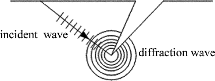
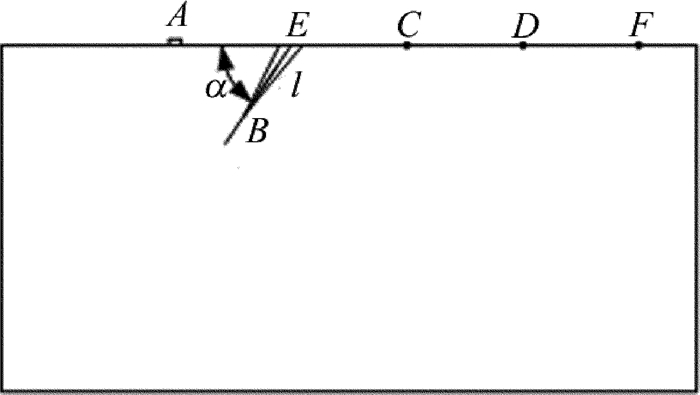
1.   理论基础
  • 图 1所示,对于各向同性的材料,入射横波到达开口裂纹尖端区域,根据惠更斯原理,裂纹尖端处的各点均可以看成发射子波的波源,其后任意时刻的子波的包络就是该时刻新的波阵面[16], 在裂纹的另一侧接收衍射波,显然,不同接收位置处横波的渡越时间亦不同。图 2中,A为激光超声横波的激励位置,C, D为不同的横波接收点,E点为裂纹中心,A点到E, C, D 3点的距离分别为l1, l2, l3,裂纹的长度和倾角分别为l, α,横波沿路径ABC和路径ABD的渡越时间分别为t1, t2,横波速率为vt,则存在下列关系:

    Figure 1.  Diffraction phenomenon

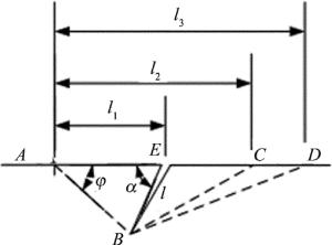
    Figure 2.  Schematic diagram for excitation and reception of shear wave

    式中,l1, l2, l3, t1, t2, vt均为已知参量,求解上述方程可得:

    在△ABE中,可进一步求得裂纹长度和角度:

    利用激光超声横波的衍射信号测量开口裂纹参量时,需要排除纵波和表面波的干扰。烧蚀机制下,半径为R的脉冲激光辐照于工件表面激励超声波,考虑宽频信号中的横波和纵波,在工件中的指向性系数[17]Dt(θ)与Dl(θ)分别为:

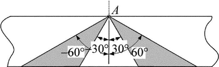
    式中,θ表示在工件内部偏离内法线的角度,规定其沿顺时针方向取正值;k是纵波速率vl与横波速率vt的比值,即vl/vtJ1则为第1类第1阶贝塞尔函数。通过选择激光光斑半径R和超声波频率f,可以使所关心的被测量区域处于纵波声场之外。图 3是盲区深度a=2.9mm, f=2.5MHz时体波声场的指向性图形。可看出,利用衍射横波检测裂纹参量的有效区域为-60°~-30°及30°~60°,如图 4中所示的阴影部分。测量过程中,应尽量使裂纹尖端处于±35°的副瓣轴线上,以获得幅值较大的衍射横波信号。表面波传播至裂纹尖端时会发生衍射,进行波形转换而产生衍射纵波及衍射横波,在接收点还会存在表面波的直通信号和绕射信号。固定接收传感器后将激励点逐渐靠近裂纹,若信号的渡越时间减少量等于激励点移动间隔与表面波速度之比时,则相应信号与激光超声表面波相关。同理,横波经衍射后的表面波信号则采用固定激励点,移动接收传感器的方法加以区分。

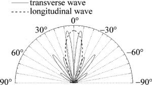
    Figure 3.  Directivity pattern of shear wave for a=2.9mm, f=2.5MHz

    Figure 4.  Effective detection range based on diffraction transverse wave method

    激励点与接收点以固定间距2s在缺陷两侧移动,当裂纹尖端处于激励点和接收点中间位置时,横波信号的渡越时间将达到最短[18],不同衍射信号的渡越时间亦存在一定的比例[19],根据上述方法及信号特征可将衍射横波信号提取出来。考虑到表面波对衍射横波的干扰,本检测方法存在着上表面盲区与下表面盲区,参照衍射时差(time of flight diffraction, TOFD)技术的检测盲区计算公式,基于保守原则,取横波速度与表面波速度二者中的较大者,相应裂纹尖端的盲区深度huhd的计算公式为[20]

    式中,tr为表面波脉冲时间宽度,tt为底面回波脉冲时间宽度,te为底面回波的渡越时间,W为工件厚度。

2.   有限元分析及测量实验
  • 为了验证上述测量方法的可行性,首先对激光超声横波在含有表面裂纹工件中的传播过程进行有限元模拟。工件的2维有限元模型如图 5所示。尺寸为60mm×30mm(长×宽),工件的左下角为坐标原点,激励区域中心点A、工件上表面裂纹的中心E、裂纹尖端B的坐标分别为:(15mm,30mm),(25mm,30mm),(21mm,24mm),激励区域的宽度为5.8mm。C, D, F为不同的接收点,坐标分别为:(35mm,30mm), (45mm,30mm), (55mm,30mm),裂纹在工件表面的宽度为2mm。由此可知,裂纹的倾角为56.3°,裂纹长度为7.2mm。工件的材质为铝,材料参量及材料中超声波的速率见表 1[21]。其中vr为表面波速率,其余参量含义同上所述。在A点施加喷溅物资作用的等效垂直力[22],其表达式[23]为:

    Figure 5.  Finite element model

    item Young’s modulus/Pa Poisson’s ratio density/(kg·m-3) vl/(m·s-1) vt /(m·s-1) vr /(m·s-1)
    value 7×10¹⁰ 0.34 2.7×10³ 6.25×10³ 3.08×10³ 2.87×10³

    Table 1.  Material parameters and ultrasonic velocity of specimen

    式中,A′为信号幅值,t表示时间。选择四节点的平面单元对工件模型进行划分。为了减少边界反射的影响,将模型的两侧设置为吸收边界。取网格大小为最小波长的1/8[24],时间积分步长则为1/(20f),求解完毕后进行后处理及时间历程分析。

    图 6为不同时刻的声场快照图。根据图 6a中波的传播速度可分为三部分,提取其各自传播路径上的节点位移数据,获取节点坐标与渡越时间,可计算出超声波的传播速度。与表 1中的数据相对比可知:沿工件内法线传播的为纵波,在工件表面传播的为表面波,其余则为横波,且其主声束轴线角度为±35.2°,与(4)式中计算的结果较为接近。图 6b显示出表面波在遇到缺陷后发生了反射,而横波则在到达裂纹尖端后发生衍射,衍射波向四周均匀传播。在激励源一侧,超声波混叠严重难以区分,应避免在同侧接收;而另一侧的衍射横波清晰可见,易于分辨。图 7中显示了接收点C, D, F的位移时间历程曲线。衍射横波幅值较大,到达各点的时间分别为7.72μs, 10.65μs, 14.05μs。实际声程分别为23.72mm, 33.22mm, 43.01mm,除以横波速率则得到理论渡越时间为7.7μs, 10.8μs, 14μs。可见,有限元分析结果和理论计算结果较为一致。

    Figure 6.  Snapshot of sound field

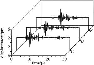
    Figure 7.  Time history curve of node displacement

    制作带有表面裂纹的6061铝质工件,工件尺寸为200mm×200mm×35mm,在其厚度方向上进行线切割加工人工缺陷,裂纹参量如表 2所示。搭建基于衍射横波的裂纹激光超声测量系统(如图 8所示),其中激光脉冲的波长为1064nm,单脉冲能量为30mJ,脉冲宽度为10ns,聚焦透镜的焦距为300mm,调节离焦量使光斑直径为1mm。此时,脉冲激光的功率密度为3.8×10⁸W/cm2,大于铝的损伤阈值7.6×107W/cm2,材料表面发生烧蚀而产生超声波。采用中心频率为2.5MHz的K1压电探头在裂纹的另一侧接收信号,使用安捷伦MSO7054B示波器进行显示与数据存储,选择标准模式其触发信号由光电二极管提供。实验中所关注的是工件上表面的开口裂纹,需要考虑上表面盲区,激励点和接收点的最小间距为12mm,根据(6)式计算得出的裂纹尖端盲区深度为2.8mm。有限元模型中的缺陷对应于试样中的缺陷2,对其进行测量时设置激光激励点距离裂纹中心10mm,分别采集距离裂纹中心15mm, 25mm处G, H两点的超声波数据,如图 9所示。得到G, H两点的横波到达时间分别为9.22μs, 12.37μs,根据(2)式及(3)式计算可得到裂纹的深度和角度分别为7.28mm, 54.5°。参照图 1中的变量定义,图 10中分别为表 2中缺陷1及缺陷6的测量数据。显然,裂纹越接近表面,横波衍射信号、表面波的衍射信号及其直通信号越容易发生混叠,当横波衍射信号与表面波的相关信号连接在一起时,本文中所提出的方法将不再适用。将裂纹的实际值与测量值列于表 2中,可见测量值与实际值的相对误差均小于5%。

    No. 1 2 3 4 5 6
    actual length/mm 5 7.2 15.8 10 18 19.7
    actual angle/(°) 37 56.3 72 0 125 120
    the measured value of length/mm 4.97 7.28 15.6 9.74 18.1 19.2
    the measured value of angle/(°) 38.2 54.5 73 0.3 123 117

    Table 2.  The actual values and the measured values of different crack parameters

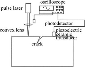
    Figure 8.  Measurement system of crack

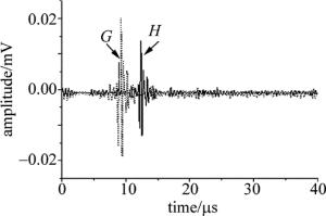
    Figure 9.  Ultrasound signals obtained from the experiment

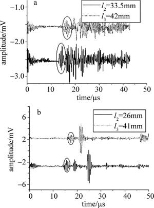
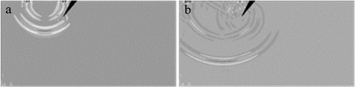
    Figure 10.  a—measurement signal for defect No.1, l1=9mm b—measurement signal for defect No.6, l1=16mm

3.   结论
  • 基于激光超声横波声场的特征,提出一种利用衍射横波测量裂纹参量的方法,分析了横波在工件中的传播过程,推导了裂纹深度和角度的计算公式。建立了工件的有限元模型,声场快照显示横波在裂纹尖端发生了较为明显的衍射,且衍射横波易于区分,说明该方法具有理论可行性。对含有裂纹的工件进行了激光超声测量,在有效的检测范围内,实验结果与实际相一致且测量误差在5%之内,因此,本方法可用于表面开口裂纹参量的测量。

Reference (24)

Catalog

    /

    DownLoad:  Full-Size Img  PowerPoint
    Return
    Return