 网站地图
网站地图


-
21世纪以来,星敏感器作为最常用的姿态测量仪器,因其具有精度高、无累计误差等特点在航天领域得到了广泛应用[1-3],如卫星姿态的确定以及星图的识别[4-8]。为了扩大星敏感器视场,采用多星敏感器在同一时间内进行姿态测量四元数融合的方法逐渐被应用在更多场合。不同星敏感器平台安装位置的差异使各位置测量结果之间存在偏差[9-10]。此外,热形变将会导致系统标定位置精度下降[11-12]。目前星敏感器三轴姿态测量精度可达到角秒级[13],而星敏感器的安装误差可达到角分级[14-15]。因此,星敏安装位置误差成为限制星敏感器测量精度的主要因素之一[16-17]。
本文中设计的多星敏感器热漂移标定位置误差检测方法,在测量多星敏感器热漂移误差的同时,建立了不同平台间位置误差的检测模型。通过该模型将位置误差造成的误差偏移量从热漂移量中剔除,从而获得更精确的热漂移标定结果。这样的检测方法可以提高系统标定精度,在该领域具有十分广阔的应用前景。
-
为了完成星敏感器多方位的地面标定,对多个星敏感器进行真空环境(温度变化范围为-25℃~60℃)下的热稳定性测试,用于确定星敏感器本身热漂移量对星敏感器测得的姿态四元数的影响。
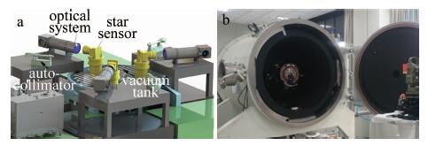
单个星敏感器热漂移标定工作原理如图 1所示。为了实现真空环境且有效隔离外界环境的影响,将星敏感器整体放置于真空罐内,并将其安装于隔振平台上,平台底部不与真空罐相连,二者安置于不同的地基上以达到隔离的目的。星敏感器标定光路起始由积分球经LED灯照射后出射均匀光,光线照射在星点板上生成点光源,通过自准直扩束光学系统出射平行光,经过真空罐壁上的光学窗口(optical window, OPW), 被星敏感器内部的阵列探测器接收, 然后模拟成无穷远处的星图,由此达到对星敏感器的标定。
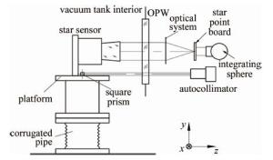
Figure 1. Working principle of single star sensor system
多星敏感器标定布置见图 2。将3个星敏感器及其标定装置围绕真空罐中心间隔120°均匀分布在真空罐内部,安装平台以同样的方式间隔分布于星敏感器下方位置。这样分布的目的在于, 完成星敏感器多方位测量标定的同时,使得标定测得的结果更加可靠,减少随机误差的影响。
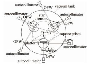
Figure 2. Multiple star sensors position error detection system
-
根据图 1和图 2所示的星敏感器热漂移标定系统原理可知,不同星敏感器之间的平台位置误差必然会对星敏感器多方位的测量结果造成一定的影响,因此建立误差检测模型十分必要。
为了测量出各平台之间的位置误差,在各个平台的中心位置安置一基准方棱镜,以此棱镜的坐标变化近似得到平台中心的坐标偏移误差。系统开始运行时,由一正对于星敏测量坐标系z向的自准直仪测量基准方棱镜的x和y初始坐标偏移,另一正对于星敏测量坐标系x向的自准直仪用于测量z向的初始偏移。单星敏感器系统内部的两棱镜需具备高度一致性,且其安装精度需高于最终所需。多星敏感器温度设置到某一值并且系统趋于稳定时,再次重复以上的测量步骤,得到基准方棱镜的稳定坐标偏移量,由此得到各平台在运行过程中产生的变形误差。各平台间的位置误差可由其变形误差的相对差值得到。
由于自准直仪安装在真空罐外侧测量,真空罐光学窗口受热而产生的热变形量会对自准直仪测量的光路产生影响,选用真空管窗口时应尽量选择热膨胀系数较好的材料,尽量减小其对测量结果的影响。
-
热漂移标定位置误差检测模型通过分别测量各个平台基准棱镜的坐标偏移量,获取其相邻垂直面即平台中心位置的姿态信息。误差检测模型计算时所用的3种坐标系如图 2所示。多星敏感器在真空罐内部安装平台上的中心坐标为m0(xm0, ym0, zm0),n0(xn0, yn0, zn0),p0(xp0, yp0, zp0)。系统开始运行前,通过误差检测模型得到的3个基准方棱镜在棱镜坐标系中的坐标位移偏差为m1(xm1, ym1, zm1),n1(xn1, yn1, zn1),p1(xp1, yp1, zp1);系统稳定时再次测量得到的坐标位移偏差为m2(xm2, ym2, zm2),n2(xn2, yn2, zn2),p2(xp2, yp2, zp2)。系统由开始到稳定运行时,测得基准棱镜沿各轴方向产生的误差矩阵C为:
$ \begin{array}{*{20}{l}} {{\bm{C}} = \left[ {\begin{array}{*{20}{l}} {\Delta {x_1}\;\;\;\;\Delta {x_2}\;\;\;\;\Delta {x_3}}\\ {\Delta {y_1}\;\;\;\;\Delta {y_2}\;\;\;\;\Delta {y_3}}\\ {\Delta {z_1}\;\;\;\;\Delta {z_2}\;\;\;\;\Delta {z_3}} \end{array}} \right] = }\\ {\left[ {\begin{array}{*{20}{l}} {{x_{{m_2}}} - {x_{{m_1}}}\;\left[ {\left( {{x_{{n_2}}} - {x_{{n_1}}}} \right) - \sqrt 3 \left( {{z_{{n_2}}} - {z_{{n_1}}}} \right)} \right]/2\left[ {\left( {{x_{{p_2}}} - {x_{{p_1}}}} \right) + \sqrt 3 \left( {{z_{{p_2}}} - {z_{{p_1}}}} \right)} \right]/2}\\ {{y_{{m_2}}} - {y_{{m_1}}}\;\;\;\;\;\;\;\;\;\;\;\;\;\;\;\;\;\;{y_{{n_2}}} - {y_{{n_1}}}\;\;\;\;\;\;\;\;\;\;\;\;\;\;\;\;\;\;\;\;\;\;\;\;\;\;\;\;\;\;\;\;\;\;\;\;{y_{{p_2}}} - {y_{{p_1}}}}\\ {{z_{{m_2}}} - {z_{{m_1}}}\;\;\left[ {\sqrt 3 \left( {{x_{{n_2}}} - {x_{{n_1}}}} \right) + \left( {{z_{{n_2}}}{ - _{{n_1}}}} \right)} \right]/2\left[ {\sqrt 3 \left( {{x_{{p_2}}} - {x_{{p_1}}}} \right) - \left( {{z_{{p_2}}} - {z_{{p_1}}}} \right)} \right]/2} \end{array}} \right]} \end{array} $
(1) 则基准棱镜坐标矩阵M的计算公式为:
$ \;\mathit{\boldsymbol{M}} = \left[ \begin{array}{l} {x_{{m_0}}} + \Delta {x_1}\;\;\;\;\;{x_{{n_0}}} + \Delta {x_2}\;\;\;\;\;{x_{{p_0}}} + \Delta {x_3}\\ {y_{{m_0}}} + \Delta {y_1}\;\;\;\;\;{y_{{n_0}}} + \Delta {y_2}\;\;\;\;\;\;{y_{{p_0}}} + \Delta {y_3}\\ {z_{{m_0}}} + \Delta {z_1}\;\;\;\;\;{z_{{n_0}}} + \Delta {z_2}\;\;\;\;\;\;{z_{{p_0}}} + \Delta {z_3} \end{array} \right] $
(2) 设变化坐标矩阵M与初始坐标矩阵M0之间的变化矩阵为A,根据MA=M0,可以得到变换矩阵A的计算公式如下:
$ \begin{array}{l} \mathit{\boldsymbol{A}} = \left[ \begin{array}{l} {a_{11}}\;\;\;\;\;{a_{12}}\;\;\;\;\;{a_{13}}\\ {a_{21}}\;\;\;\;\;{a_{22}}\;\;\;\;\;{a_{23}}\\ {a_{31}}\;\;\;\;\;{a_{32}}\;\;\;\;\;{a_{33}} \end{array} \right] = \\ {\left[ \begin{array}{l} {x_{{m_0}}} + \Delta {x_1}\;\;\;{x_{{n_0}}} + \Delta {x_2}\;\;\;{x_{{p_0}}} + \Delta {x_3}\\ {y_{{m_0}}} + \Delta {y_1}\;\;\;\;{y_{{n_0}}} + \Delta {y_2}\;\;\;{y_{{p_0}}} + \Delta {y_3}\\ {z_{{m_0}}} + \Delta {z_1}\;\;\;\;{z_{{n_0}}} + \Delta {z_2}\;\;\;{z_{{p_0}}} + \Delta {z_3} \end{array} \right]^{ - 1}}\left[ \begin{array}{l} {x_{{m_0}}}\;\;\;{x_{{n_0}}}\;\;\;{x_{{p_0}}}\\ {y_{{m_0}}}\;\;\;{y_{{n_0}}}\;\;\;{y_{{p_0}}}\\ {z_{{m_0}}}\;\;\;{z_{{n_0}}}\;\;\;{z_{{p_0}}}\; \end{array} \right] \end{array} $
(3) 根据星敏感器标定系统测量结果,由3个星敏感分别测得的星图姿态四元数分别为:
$ \left\{ \begin{array}{l} {\mathit{\boldsymbol{q}}_m} = {\left[ {{q_{{m_0}}}\;\;\;{q_{{m_1}}}\;\;\;{q_{{m_2}}}\;\;\;{q_{{m_3}}}} \right]^{\rm{T}}} = {\left[ {{q_{{m_0}}}\;\;\;{{\mathit{\boldsymbol{\hat q}}}_m}} \right]^{\rm{T}}}\\ {\mathit{\boldsymbol{q}}_n} = {\left[ {{q_{{n_0}}}\;\;\;{q_{{n_1}}}\;\;\;{q_{{n_2}}}\;\;\;{q_{{n_3}}}} \right]^{\rm{T}}} = {\left[ {{q_{{n_0}}}\;\;\;{{\mathit{\boldsymbol{\hat q}}}_n}} \right]^{\rm{T}}}\\ {\mathit{\boldsymbol{q}}_p} = {[{q_{{p_0}}}\;\;\;\;{q_{{p_1}}}\;\;\;{q_{{p_2}}}\;\;\;{q_{{p_3}}}]^{\rm{T}}} = {[{q_{{p_0}}}\;\;\;{{\mathit{\boldsymbol{\hat q}}}_p}]^{\rm{T}}} \end{array} \right. $
(4) 式中, q为四元数标部,$ {\mathit{\boldsymbol{\hat q}}} $为四元数矢部。根根据角距测量原理,将星敏感器姿态偏移角等效为坐标偏移变化,则变化后的姿态四元数矢部矩阵为:
$ {\left[ \begin{array}{l} {{\mathit{\boldsymbol{\hat q}}}_{{m_1}}}\\ {{\mathit{\boldsymbol{\hat q}}}_{{n_1}}}\\ {{\mathit{\boldsymbol{\hat q}}}_{{p_1}}} \end{array} \right]^{\rm{T}}} = \mathit{\boldsymbol{A}}{\left[ \begin{array}{l} {{\mathit{\boldsymbol{\hat q}}}_m}\\ {{\mathit{\boldsymbol{\hat q}}}_n}\\ {{\mathit{\boldsymbol{\hat q}}}_p} \end{array} \right]^{^{\rm{T}}}} = \left[ \begin{array}{l} {a_{11}}\;\;\;\;{a_{12}}\;\;\;\;{a_{13}}\\ {a_{21}}\;\;\;\;{a_{22}}\;\;\;\;{a_{23}}\\ {a_{31}}\;\;\;\;{a_{32}}\;\;\;\;{a_{33}} \end{array} \right]\cdot{\left[ \begin{array}{l} {{\mathit{\boldsymbol{\hat q}}}_m}\\ {{\mathit{\boldsymbol{\hat q}}}_n}\\ {{\mathit{\boldsymbol{\hat q}}}_p} \end{array} \right]^{^{\rm{T}}}} $
(5) 由此得到剔除星敏感器相互间位置误差的姿态四元数矩阵结果如下:
$ {\left[ {{\mathit{\boldsymbol{q}}_{{m_1}}}\;\;\;\;{\mathit{\boldsymbol{q}}_{{n_1}}}\;\;\;\;{\mathit{\boldsymbol{q}}_{{p_1}}}} \right]^{\rm{T}}} = {\left[ \begin{array}{l} {\mathit{q}_{{m_0}}}\;\;\;\;\mathit{\boldsymbol{A}}{{\mathit{\boldsymbol{\hat q}}}_m}\\ {\mathit{q}_{{n_0}}}\;\;\;\;\mathit{\boldsymbol{A}}{{\mathit{\boldsymbol{\hat q}}}_n}\\ {\mathit{q}_{{p_0}}}\;\;\;\;\mathit{\boldsymbol{A}}{{\mathit{\boldsymbol{\hat q}}}_p} \end{array} \right]^{\rm{T}}} $
(6) -
为了验证多星敏感器热漂移标定位置误差检测模型的有效性,设置了试验对其检测精度进行计算。用于试验的星敏感器参量设置如表 1所示。
Table 1. Design parameters for the star sensors
parameters index field of view 12°×12° focal length 1121.54mm equipment length ≤1000mm angular accuracy ≤10″ temperature range -25℃~60℃ 为了减小初始安装位差以及平台自身制造误差带来的影响,试验初设3个星敏感平台位于同一平面上,且不存在倾斜等可能导致误差的情形。根据标定系统要求设置工作环境为真空,星敏感器固定安装面为平台底面,其温度变化范围为-25℃~60℃,且各星敏感器之间温度差值设置为±1℃,在温度变化范围内每隔1℃获取一次数据;平台安装面温度设置为恒温20℃。试验装置图如图 3所示。
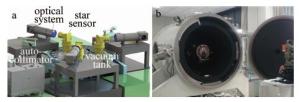
Figure 3. Test device arrangement a—internal three-dimensional layout diagram b—experimental actual device layout
试验获得的各个基准棱镜变形偏移量结果见图 4。将上述结果所示的258组数据代入位置误差模型的(1)式~(5)式进行计算,得到多星敏感器热漂移标定时产生的姿态四元数极限偏差如列表 2所示。

Figure 4. Position deformation offset results
Table 2. Deformation angle results of different temperature
temperature/℃ prism offset around the x axis/(″·℃-1) offset around the y axis/(″·℃-1) Offset around the z axis/(″·℃-1) -25 m -31.2349134 -0.0235792 0.3789641 n -39.3412561 -0.0155460 -24.1372848 p -38. 5584741 0.0609176 -23.4569765 60 m -24.6603975 0.0150 403 0.0159451 n -34.7124605 -0.0492412 -23.5409127 p -35.6208196 0.0143522 -23.7295659 计算结果显示,多星敏感器标定系统在-25℃和60℃时分别达到单位温度内的姿态极限偏移,多星敏感器由于位置误差造成的绕x, y, z轴的最小变化量分别为-24.660″/℃, 0.015″/℃, 0.159″/℃,而最大变化量分别为-39.341 ″/℃, -0.060″/℃, -24.137″/℃。根据数据可知,星敏感器平台位置误差在x向和z向更为敏感,会对星敏感器最终姿态偏移测量结果产生较大影响。当星敏感器热漂移标定精度要求控制在0.05°/℃时,经过误差检测模型的计算结果可比未检测前的精度提高至少11%,证实了该误差检测模型有效提高了系统标定精度。
-
对多星敏感器热漂移标定位置误差检测方法进行了研究。根据多星敏感器标定系统的工作原理,设计了多星敏感器的位置误差检测模型,并根据此模型计算出由位置误差造成的姿态偏移量分别为-24.660″/℃, 0.015″/℃, 0.159″/℃,而最大变化量分别为-39.341 ″/℃, -0.060″/℃, -24.137″/℃。最后通过仿真试验及其计算结果证实:位置误差检测模型能够有效提高系统热漂移标定的精度,简化了标定系统的复杂程度。
多星敏感器地面热漂移标定位置误差检测研究
Method research of multiple star sensors ground thermal drift calibration position error detection
-
摘要: 为了减少多个星敏感器地面热漂移标定时受到不同安装平台的位置误差影响, 采取一种多星敏感器地面热漂移标定位置误差检测方法,进行了理论分析和实验验证,取得了-25℃~60℃真空状态下系统中基准方棱镜变形的位置偏移量数据,并进行了标定位置误差精度分析。结果表明,多星敏感器位置绕各轴产生的最大偏移量分别为-39.341″/℃, -0.060″/℃, -24.137″/℃,通过建立误差检测模型对位置误差进行计算,将其从姿态测量结果的偏移量中剔除后获得更准确的星敏感器姿态测量四元数,剔除位置误差后的系统精度至少提高了11%。该研究在提高星敏感器热漂移标定精度方面具有很好的应用前景。Abstract: In order to reduce the affect of the deformation offset of different installation platforms on the ground thermal drift calibration of multiple star sensors, a multiple star sensor ground thermal drift calibration position error detection method was proposed. Theoretical analysis and experimental verification were carried out. The position deviation data of the reference square prism deformation in the system under the vacuum of -25℃~60℃ was obtained. And the accuracy analysis of calibration position error was carried out.The results show that, the maximum offsets of the multi-star sensor positions around each axis are -39.341″/℃, -0.060″/℃, and -24.137″/℃, repectively. By establishing the error detection model which was established according to the method of measuring position error, the position error was removed from the offset of the attitude measurement result to obtain a more accurate star sensor attitude measurement quaternion. And the system accuracy after removing the position error was improved by at least 11%, which means it has a good application prospect in improving the accuracy of star sensor thermal drift calibration.
-
Figure 3. Test device arrangement a—internal three-dimensional layout diagram b—experimental actual device layout
Table 1. Design parameters for the star sensors
parameters index field of view 12°×12° focal length 1121.54mm equipment length ≤1000mm angular accuracy ≤10″ temperature range -25℃~60℃  下载: 导出CSV
Table 2. Deformation angle results of different temperature
temperature/℃ prism offset around the x axis/(″·℃-1) offset around the y axis/(″·℃-1) Offset around the z axis/(″·℃-1) -25 m -31.2349134 -0.0235792 0.3789641 n -39.3412561 -0.0155460 -24.1372848 p -38. 5584741 0.0609176 -23.4569765 60 m -24.6603975 0.0150 403 0.0159451 n -34.7124605 -0.0492412 -23.5409127 p -35.6208196 0.0143522 -23.7295659
下载: 导出CSV
-
[1] LIANG B, ZHU H L, ZHANG T, et al. Research status and development tendency of star tracker technique[J]. Chinese Optics, 2016, 9(1):16-29(in Chinese). [2] LI X P, SUN Sh Y, ZHENG X J, et al. On-orbit real time installation matrix calibration method for high accuracy star trackers [J]. Infrared and Laser Engineering, 2018, 47(12): 205-211(in Chinese). [3] CHEN W X, WANG L, ZHENG T, et al. An automatic measurement method for installation error of star sensor [J].China Measurement, 2019, 45(2): 111-115(in Chinese). [4] GAO Q, REN Zh B, SUN A M, et al. Research on satellite attitude estimation based on star sensor[J].Navigation Positioning and Timing, 2018, 5(1):42-47(in Chinese). [5] XIONG Y Zh, WU Y P, CHENG H Y. Attitude determination accuracy of multi-head star tracker based on star-image fusion [J].Journal of Chinese Inertial Technology, 2016, 24(5):612-618(in Chinese). [6] SONG L L, ZHANG T, LIANG B, et al. Attitude determination method based on star sensor [J]. Journal of System Simulation, 2010, 22(s1):1-6(in Chinese). [7] XIE J F. The critical technology of data processing of satellite attitude determination based on star sensor[D]. Wuhan: Wuhan University, 2010: 80-84(in Chinese). [8] DUAN Y H, GUAN L. High precision attitude measurement and Calibration method of spacecraft based on precision star sensor [J]. Computer Measurement and Control, 2019, 27(11):1-5(in Chinese). [9] LONG L, LI Z F. 3-D position measurement algorithm based on laser displacement sensors[J].Laser Technology, 2017, 41(4):531-536(in Chinese). [10] JIANG X D, YU J Y, ZHU L K. Research of combined navigation technology based on position sensitive detectors[J] Laser Technology, 2019, 43(3):335-340(in Chinese). [11] JIN H, ZHAI Zh Y, DU W F, et al. Experimental analysis of star sensor thermostability [J]. Chinese Journal of Lasers, 2020, 47(2):0204001(in Chinese). [12] XU Y X, CHEN Q. Analysis and compensation of the star sensor's HFE in the satellite attitude determination [J].Pattern Recognition and Simulation, 2016, 35(10):109-113(in Chinese). [13] WANG H L, HE Y Y, LU J H, et al. Ground calibration method of installation error for star sensor based on three positions method[J]. Infrared and Laser Engineering, 2016, 45(11): 327-332(in Chinese). [14] LIAN Y Y, ZHANG Ch, ZHAN Y H, et al. Star apparent position calculation and updating method of attitude determination [J]. Science of Surveying and Mapping, 2015, 40(12): 134-139(in Chinese). [15] WANG X, CAI Sh J, WU L H, et al. Research on calibration technology of star sensor installation error angle[J]. Navigation Position-ing and Timing, 2019, 6(3): 125-130(in Chinese). [16] YE T, YANG F. Autonomous calibration of star sensors based on nonlinear optimization algorithm[J]. Optics and Precision Engineering, 2017, 25(9): 2483-2489(in Chinese). doi: 10.3788/OPE.20172509.2483 [17] ZHANG X, WANG H L, LU J H, et al. Calibration method of optical errors for star sensor based onparticle swarm optimization algorithm[J].Infrared and Laser Engineering, 2017, 46(10): 172-179(in Chinese). -

 点击查看大图

图(4) / 表(2)
计量
- 文章访问数: 7256
- HTML全文浏览量: 4754
- PDF下载量: 18
- 被引次数: 0
