 网站地图
网站地图


-
偏振是光的一个重要特性。过去大多数的研究主要集中在偏振态均一分布的标量光场领域,例如线偏振、圆偏振和椭圆偏振。近些年来,矢量光场的产生与检测开始引起科学家们的兴趣,一个特定的例子就是径向偏振光[1]。径向偏振光有着非常好的对称性,其横截面上的电场矢量关于光轴对称并且始终和径向平行; 同时轴上光强为零,所以一般称其为面包圈结构。基于这种独特的偏振模式和光束特性,人们对于径向偏振光的研究也越来越深入,而随之发现的一系列研究成果也表明:在对粒子的俘获[2]与加速[3]、激光切割[4]、光刻[5]和光学存储[6]等领域中,径向偏振光都可能具有明显的优势。
自1972年首次得到径向偏振光以来[7],已经出现了许多产生径向偏振光的方法[8-9]。这些方法主要可以分为两类:腔内法和腔外法。腔内法指通过偏振选择器件使激光器直接以径向偏振光模式振荡输出,例如轴向双折射元件法[10]、锥形布儒斯特镜法[11]和组合轴锥镜法[12]。腔外法指通过偏振转换器件在自由空间里把更常见的标量光(通常为线偏或圆偏)转换为径向偏振光,例如空间光调制器法[13]、s波片法[14]和螺旋相位板法[15]等。腔内法中的偏振选择器件往往结构精密,对制造工艺的要求很高,成本高昂,这使其难以被广泛使用。腔外法中的空间光调制器、s波片和螺旋相位板价格也比较昂贵。基于这种情况,设计了一种利用组合半波片和组合线偏振片在腔外把线偏振光转换为径向偏振光的方法,具有结构简单、灵活可靠、成本低廉的优点。
尽管产生径向偏振光的方法很多,但如何对径向偏振光进行全面的检测[16-18]还在探索之中。矢量光束的一个重要特征就是偏振分布和空间分布的不可分离耦合,而空间变化的偏振意味着使矢量光束通过偏振器后所观察到的光斑图案能随着偏振器的透射轴方向的改变而变化,一般称之为旋转检偏器法。旋转检偏器法能很简便地对待测光束光截面的偏振分布进行定性检测,但无法得到径向分量分布的定量数据。此外,在某一具体的时刻时,虽然检偏器后的两个扇形光斑的偏振态都是线偏振,但实际上两者的相位是相反的,即存在π相位差,而仅仅通过检偏器是无法检测出这一点的。而本文中基于经典斯托克斯参量测量法[19-20]和马赫-曾德尔干涉原理对以上两点均进行了检测。
-
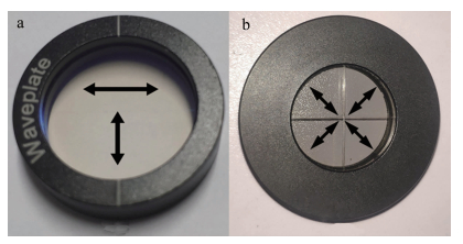
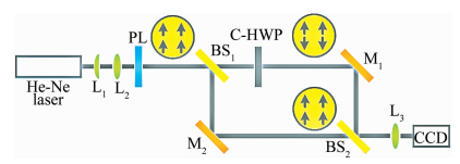
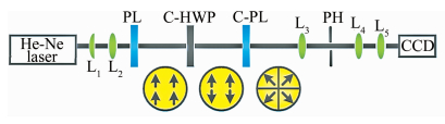
图 1是本文中提出的利用组合半波片和组合线偏振片把线偏光转换为径向偏振光的系统示意图。首先氦氖激光通过由L1和L2两个凸透镜组成的望远镜系统进行扩束准直,然后入射到透射轴竖直的起偏器(polarizer, PL)上转变成竖直方向的线偏振光。组合半波片(combined half-wave-plate,C-HWP)如图 2a所示, 由上下两个半圆半波片组合而成,且两个半波片的主轴方向一个沿水平,另一个沿竖直,如箭头所示。竖直线偏光通过组合半波片后上下两部分的光会产生相位的延迟。组合线偏振片(combined polarizer,C-PL)如图 2b所示, 由4个分布在四象限的扇形线偏振片组合而成,每个线偏振片的偏振方向与其角平分线方向平行,如箭头所示。经过组合半波片的光在通过组合线偏振片时,其偏振方向与组合线偏振片4个分块的透射方向都有着45°的角度差,通过简单的光束分解就能得到输出光为径向偏振光。接着光束通过由透镜L3、小孔(pin hole, PH)和透镜L4构成的滤波系统,最后经透镜L5被聚焦到CCD上。显然,当组合线偏振片的分块数量越多,例如8块、16块,输出光束也会越接近理想的径向偏振光。

Figure 1. Radially polarized beams generating system
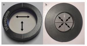
Figure 2. Combined optical device
-
图 3a是系统输出光束的总强度分布, 图 3b~图 3e是通过不同角度的检偏器后的强度分布。每个箭头代表检偏器透射轴的方向,即0°, 45°, 90°和135°。由于组合线偏振片只有4个分块,当检偏器偏振方向位于水平或竖直时,光斑分布不变但强度减弱,如图 3b和图 3d所示。当检偏器旋转到或时,光斑分布为两侧都是扇形的亮斑,且两侧扇形的角平分线和检偏器的偏振方向一致,如图 3c和图 3e所示。该结果很好地反映了系统输出光束的偏振分布。
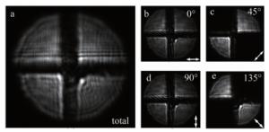
Figure 3. Measured intensity distribution of the laser beam
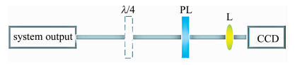
任何光的偏振态都可以用4个斯托克斯参量(S0, S1, S2, S3)来表征[21],通过这4个参量能够得到非常全面的偏振特性参量,例如偏振度、偏振方向、椭圆率和偏振类型等,图 4是用经典斯托克斯参量测量法测量径向偏振光纯度的示意图。不插入λ/4波片,并使线偏振片偏振方向分别为0°, 45°和90°时,可以得到前3个参量S0,S1和S2; 当线偏振片处于45°偏转,同时插入快轴方向沿水平的λ/4波片得到第4个参量S3,就能得到光的偏振方向ψ和椭圆率角χ:ψ=arctan(S2/S1)/2, χ=arcsin(S3/S0)/2。
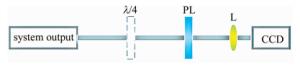
Figure 4. Classical measurement of the Stokes parameters
光束波面上任意一点的径向分量表达式为:
$ {E_{\rm{r}}} = {E_x}\text{cos}\varphi + {E_y}\text{sin}\varphi $
(1) 式中,Ex, Ey, φ分别为该点振幅的水平分量、竖直分量和在波面上的方位角。对于径向偏振光而言,偏振纯度指沿径向的光束能量与总能量的比值,可以表示为:
$ \begin{array}{*{20}{c}} {\eta = \frac{{\smallint {{\left| {{E_{\rm{r}}}} \right|}^2}{\rm{d}}S}}{{\smallint {{\left| \boldsymbol{E} \right|}^2}{\rm{d}}S}} = }\\ {\frac{{\smallint [{E_x}^2{\rm{co}}{{\rm{s}}^2}\varphi + {E_y}^2{\rm{si}}{{\rm{n}}^2}\varphi + {\rm{Re}}({E_x}^*{E_y}){\rm{sin}}(2\varphi )]{\rm{d}}\varphi }}{{\smallint {S_0}{\rm{d}}S}} = }\\ {\frac{{\smallint [({S_0} + {S_1}){\rm{co}}{{\rm{s}}^2}\varphi + ({S_0} - {S_1}){\rm{si}}{{\rm{n}}^2}\varphi + {S_2}{\rm{sin}}(2\varphi )]{\rm{d}}\varphi }}{{2\smallint {S_0}{\rm{d}}S}}} \end{array} $
(2) 式中, S是面积,E为电场矢量。从表 1可知,当组合线偏振片的分块数为4时,理论偏振纯度为81.8%。根据CCD接收到的图像可以得到光截面上每个像素点的斯托克斯参量,进而计算出实际径向偏振光的纯度为80.5%,与理论值十分接近。
Table 1. Polarized purity at different numbers of C-PL
numbers of C-PL 4 8 16 N polarized purity 81.8% 95.0% 98.8% 使用旋转检偏器法和经典斯托克斯参量测量法都能检测出径向偏振光是局部线偏振的,但是它们并不能检测出在同一时刻t时径向偏振光对称区域的相位关系。图 5是基于马赫-曾德尔干涉原理对系统输出光束进行相位延迟检测的原理图。但实际上,由于组合半波片和组合线偏振片的工艺问题导致输出光束的偏振角度略有偏移,同时滤波系统也无法完全消除胶合位置引入的衍射效应(如图 3a所示)。为了避免这些衍射条纹对相位延迟检测的实验现象的干扰,最终使用了图 6中的测量方案。
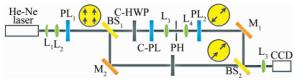
Figure 5. Ideal set-up to detect π phase delay
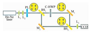
Figure 6. Experimental set-up to detect π phase delay
马赫-曾德尔干涉仪上臂的透射光场上下两部分可以分别表示为:
$ \left\{ \begin{array}{l} {E_{{\rm{up}}}} = {E_0}{\rm{exp}}[{\rm{j}}(k{z_1} - \omega t)]\\ {E_{{\rm{down}}}} = {E_0}{\rm{exp}}[{\rm{j}}(k{z_1} - \omega t + {\rm{ \mathit{ π} }})] \end{array} \right. $
(3) 马赫-曾德尔干涉仪下臂的透射光场也分割成上下两部分用于计算,表达式为:
$ \begin{array}{*{20}{c}} {E' = {E_0}{\rm{exp}}\{ {\rm{j}}[k({z_2}{\rm{cos}}\alpha + x{\rm{sin}}\alpha ) - \omega t]\} \approx }\\ {{E_0}{\rm{exp}}[{\rm{j}}(k{z_2} + kx\alpha - \omega t)]} \end{array} $
(4) 式中, E0,k,ω分别表示振幅、波数、频率; z1和z2分别为分束镜(beam splitter, BS)BS1沿干涉仪上臂和下臂到CCD接收面的距离; x为CCD接收面的横坐标(如图 7b箭头所示); α为干涉仪上下臂两束光的夹角。通过光波叠加可以得出合束后的光场上下两部分光强表达式分别为:
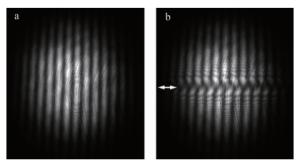
Figure 7. Measured intensity distribution after the BS2
$ \left\{ \begin{array}{l} {I_{{\rm{up}}}} = 4{I_0}{\rm{co}}{{\rm{s}}^2}\left( {\frac{{{\delta _1}}}{2}} \right)\\ {I_{{\rm{down}}}} = 4{I_0}{\rm{co}}{{\rm{s}}^2}\left( {\frac{{{\delta _2}}}{2}} \right) \end{array} \right. $
(5) 式中,I0=|E0|2,是单个光波的强度; δ1=k(z2-z1)+kxα,是上半部分两光波的位相差; δ2=δ1+π,是下半部分两光波的位相差。
当δ1=2mπ(m为整数)时,可得:
$ \left\{ \begin{array}{l} {I_{{\rm{up}}}} = 4{I_0}\\ {I_{{\rm{down}}}} = 0 \end{array} \right. $
(6) 当δ1=(2m+1)π时,可得:
$ \left\{ \begin{array}{l} {I_{{\rm{up}}}} = 0\\ {I_{{\rm{down}}}} = 4{I_0} \end{array} \right. $
(7) (6) 式和(7)式表明, 输出光束上下两部分光斑的干涉增强点和干涉相消点恰好是相反的,即上下两部分的干涉条纹明暗相对。图 7是一般马赫-曾德尔干涉和实际π相位延迟检测的光束输出图像。
-
提出了一种基于组合半波片和组合线偏振片的新型径向偏振光产生方法,成功输出了径向偏振光,偏振纯度为80.5%,并检测出光束对称区域的线偏振相位差为π。实验结果验证了该方法的可行性,下一步将使用更多分块数的组合线偏振片,以得到更高纯度的径向偏振光输出。
一种径向偏振光的产生方法
A method for generating radially polarized beams
-
摘要: 为了产生径向偏振光,采用组合半波片和组合线偏振片在腔外对线偏振光做极化整形的方法,进行了理论分析和实验验证。为检测该径向偏振光产生系统的性能,采用旋转检偏器法对输出光束的偏振分布进行了检测,并用经典斯托克斯参量测量法计算了偏振纯度,最后基于马赫-曾德尔干涉的原理,检测了径向偏振光对称区域的线偏振相位关系。结果表明,当组合线偏振片为4个分块时,获得了偏振纯度为80.5%的径向偏振光,并检测出光斑对称区域的线偏振相位差为π。这一结果对在低成本条件下产生高纯度的径向偏振光是有帮助的。Abstract: In order to generate radially polarized beams, a method of polarization shaping of linearly polarized beams outside the cavity by a combined half-wave-plates and a combined linear polarizer was put forward. In order to detect the performance of the generating system, the polarization distribution of the output beam was detected by the rotary polarizer method, and its polarization purity was calculated by the classical stokes parameters measurement method. Finally, based on the Mach-Zehnder interference principle, the linear polarization phase relationship of the symmetric region of the radially polarized beams was detected. The results show that when the combined linearly polarizer is divided into four segments, the radially polarized beams with a polarization purity of 80.5% is obtained, and the linear polarization phase difference of the symmetric region is π. The result is helpful to produce the radially polarized light with high purity at low cost.
-
Figure 3. Measured intensity distribution of the laser beam
a—total intensity distribution b~e—measured intensity distribution after the PL in horizontal
Figure 7. Measured intensity distribution after the BS2
a—without phase delay b—with phase delay
Table 1. Polarized purity at different numbers of C-PL
numbers of C-PL 4 8 16 N polarized purity 81.8% 95.0% 98.8%  下载: 导出CSV
-
[1] ZHAN Q. Cylindrical vector beams:From mathematical concepts to applications[J].Journal of Systems Science & Complexity, 2009, 27(5):899-910. [2] KOZAWA Y, SATO S. Optical trapping of micrometer-sized dielectric particles by cylindrical vector beams[J].Optics Express, 2010, 18(10):10828-10833. [3] MARCEAU V, APRIL A, PICHÉ M. Electron acceleration driven by ultrashort and nonparaxial radially polarized laser pulses[J].Optics Letters, 2012, 37(13):2442-2445. doi: 10.1364/OL.37.002442 [4] FU E Sh. Influence of beam polarization on laser cutting efficiency[J].Laser & Optoelectronics Progress, 2003, 40(2):3-8 (in Chinese). [5] CHENG B H, LAN Y C, TSAI D P. Breaking optical diffraction limitation using optical hybrid-super-hyperlens with radially polarized light[J].Optics Express, 2013, 21(12):14898. doi: 10.1364/OE.21.014898 [6] ZHANG Y, BAI J, ZHANG Y, et al. Improving the recording ability of a near-field optical storage system by higher-order radially polarized beams[J].Optics Express, 2009, 17(5):3698-3706. doi: 10.1364/OE.17.003698 [7] MUSHIAKE Y, MATSUMURA K, NAKAJIMA N. Generation of radially polarized optical beam mode by laser oscillation[J].Proceedings of the IEEE, 1972, 60(9):1107-1109. doi: 10.1109/PROC.1972.8865 [8] TANG X Ch, GAO J C, WANG K, et al. Generation of a radially polarized light and its applications[J].Laser & Optoelectronics Progress, 2013, 50(3):030001(in Chinese). [9] WANG Zh H, LI J S. The generation of a radially polarized beam and its application in the modern optics[J].Laser Journal, 2009, 30(1):8-10(in Chinese). [10] YONEZAWA K, KOZAWA Y, SATO S. Generation of a radially polarized laser beam by use of the birefringence of a c-cut Nd:YVO4 crystal[J].Optics Letters, 2006, 31(14):2151-2153. doi: 10.1364/OL.31.002151 [11] KOZAWA Y, SATO S. Generation of a radially polarized laser beam by use of a conical Brewster prism[J].Optics Letters, 2005, 30(22):3063-3065. doi: 10.1364/OL.30.003063 [12] WANG Zh Y, HU Y Y, LI B. Design of combined axicon for high power radial polarized light[J].Laser Technology, 2017, 41(6):846-851(in Chinese). [13] TIDWELL S C, FORD D H, KIMURA W D. Generating radially polarized beams interferometrically[J].Applied Optics, 1990, 29(15):2234-2239. doi: 10.1364/AO.29.002234 [14] LIN D, BAKTASH N, BERENDT M, et al. Radially- and azimuthally- polarized nanosecond Yb-doped MOPA system incoporating temporal shaping[J].Optics Letters, 2016, 42(9):1740-1744. [15] PHUA P B, LAI W J, LIM Y L, et al. Mimicking optical activity for generating radially polarized light[J].Optics Letters, 2007, 32(4):376-378. doi: 10.1364/OL.32.000376 [16] CHENG H, HAN J, GU J D, et al. Research on radial polarized light and method of detection[J].Electro-Optic Technology Application, 2015, 30(3):62-65(in Chinese). [17] PENG H P, YANG C, LU Sh, et al. Radially polarized beam purity detection and evaluation of polarization distribution characteristics[J].Infrared and Laser Engineering, 2019, 48(5):0506007(in Chinese). doi: 10.3788/IRLA201948.0506007 [18] ROSALES-GUZMÁN C, NDAGANO B, FORBES A. A review of complex vector light fields and their applications[J].Journal of Optics, 2018, 20(12):123001. doi: 10.1088/2040-8986/aaeb7d [19] SCHAEFER B, COLLETT E, SMYTH R, et al. Measuring the Stokes polarization parameters[J].American Journal of Physics, 2007, 75(2):163-165. doi: 10.1119/1.2386162 [20] ZHOU Zh H, ZHU L Q. Measurement method of polarization state of vector beams based on Stokes parameters[J].Laser & Infrared, 2016, 46(6):742-746 (in Chinese). [21] ZENG L W, CAI Y J, TAN Ch Sh, et al. Optimization of Stokes optical polarization measurement system[J].Laser Technology, 2017, 41(1):74-78 (in Chinese). -

 点击查看大图
图(7) / 表(1)
计量
- 文章访问数: 6597
- HTML全文浏览量: 4967
- PDF下载量: 33
- 被引次数: 0
